10–26
Troubleshooting
Publication
1747-6.2
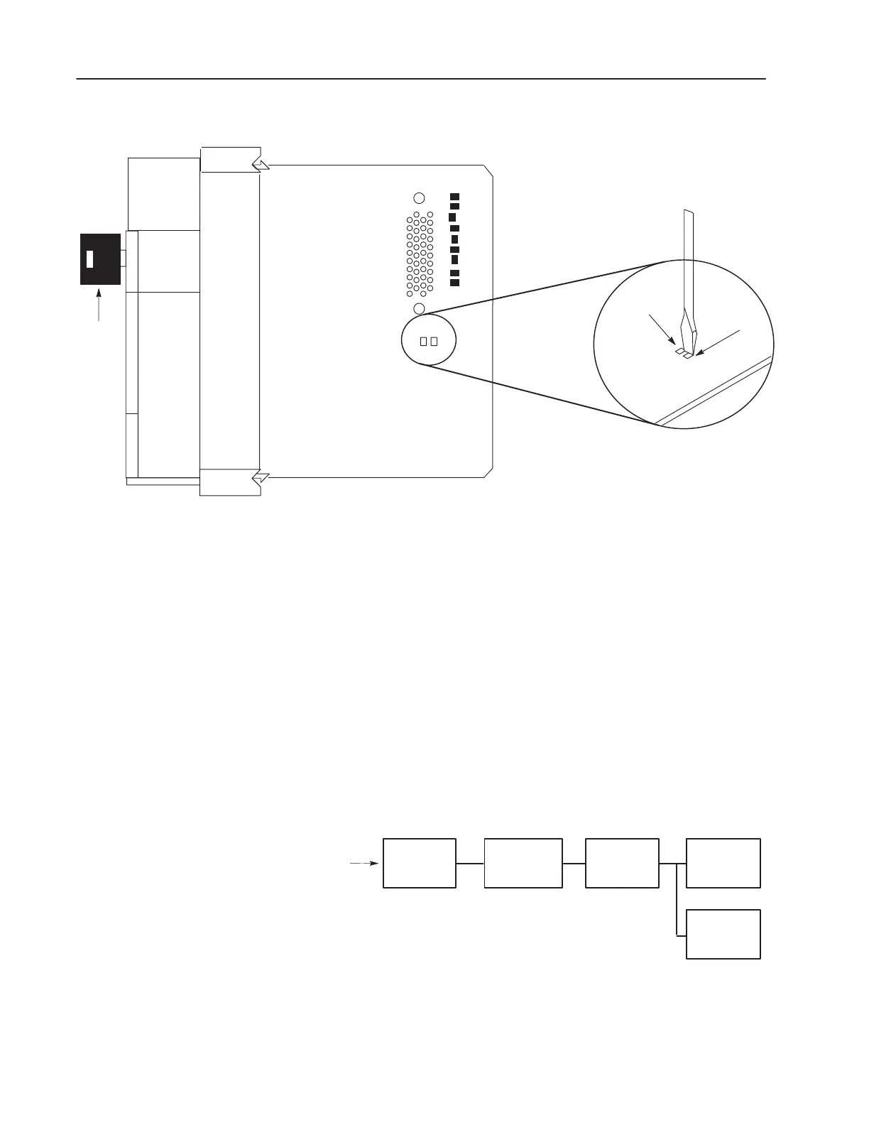
Right Side View
Keyswitch
GND VBB
Mother Board
Mother Board
VBB
GND
SLC 5/04 (1747-L541, 1747-L542, and 1747-L543)
SLC 5/05 (1747-L551, 1747-L552, and 1747-L553)
The following will assist you in troubleshooting your input modules.
Input Circuit Operation
An input circuit responds to an input signal in the following manner:
1. An input filter removes false signals due to contact bounce or
electrical interference.
2. Opto-electrical isolation protects the input circuit and backplane
circuits by isolating logic circuits from input signals.
3. Logic circuits process the signal.
4. An input LED turns on or off indicating the status of the
corresponding input device.
Input
Input
Conditioning
Opto-Electrical
Isolation
Logic Circuits Backplane
LED
Troubleshooting Your
Input Modules

 Loading...


