6–9
Installing Your Hardware Components
Publication
1747-6.2
POWER
Fuse
POWER
100/120
V
olts
200/240 V
olts
Fuse
85–132V ac
170–265V ac
Jumper
Selection
Jumper
Selection
POWER
POWER
120/240V ac
V ac NEUT
CHASSIS GROUND
dc NEUT
+ 24V dc
CHASSIS GROUND
JUMPER
170–265V ac
L2
NEUTRAL
L185–132/170–265
85–132V ac
CHASSIS GROUND
+125V dc
dc NEUT
CHASSIS GROUNDCHASSIS GROUND
PWR OUT COM
PWR OUT COM
PWR OUT +24V dc
PWR OUT +24V dc
PWR OUT +24V dc
PWR OUT COMMON
NOT USED
NOT USED
User
Power
User
Power
User
Power
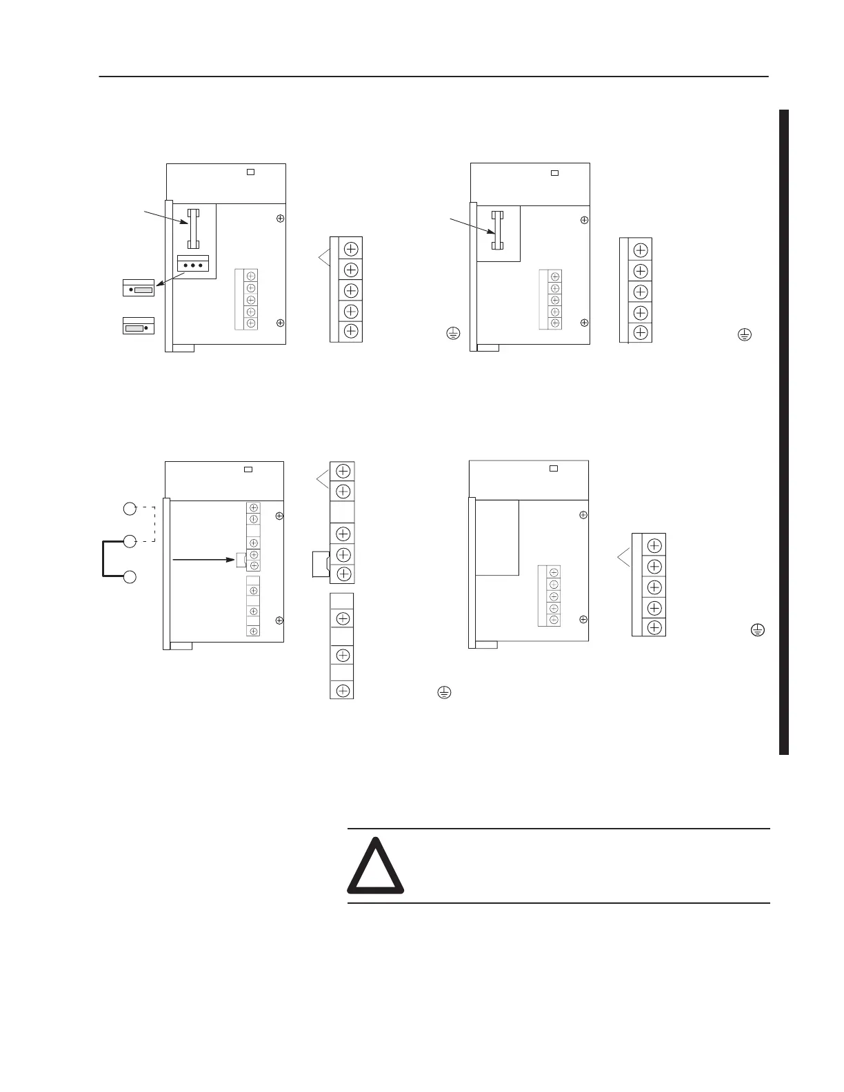
1746-P1 and -P2
1746-P4 1746-P5
1746-P3
4. Remove the warning label from the top of the power supply.
5. Connect line power to the power supply.
!
ATTENTION: If you have a 1746-P3, see page 3–5
for special grounding considerations.
On the 1746-P1 and -P2 power supply, use the PWR OUT + 24 VDC
and PWR OUT COM terminals to power sensors. The terminals
provide an isolated, nonfused, 200 mA, 24V dc power supply.

 Loading...


