All rights reserved. Reproduction of this document, even in part, is only permitted with the approval of alpitronic Srl.
6.4.4. Plug lock failed
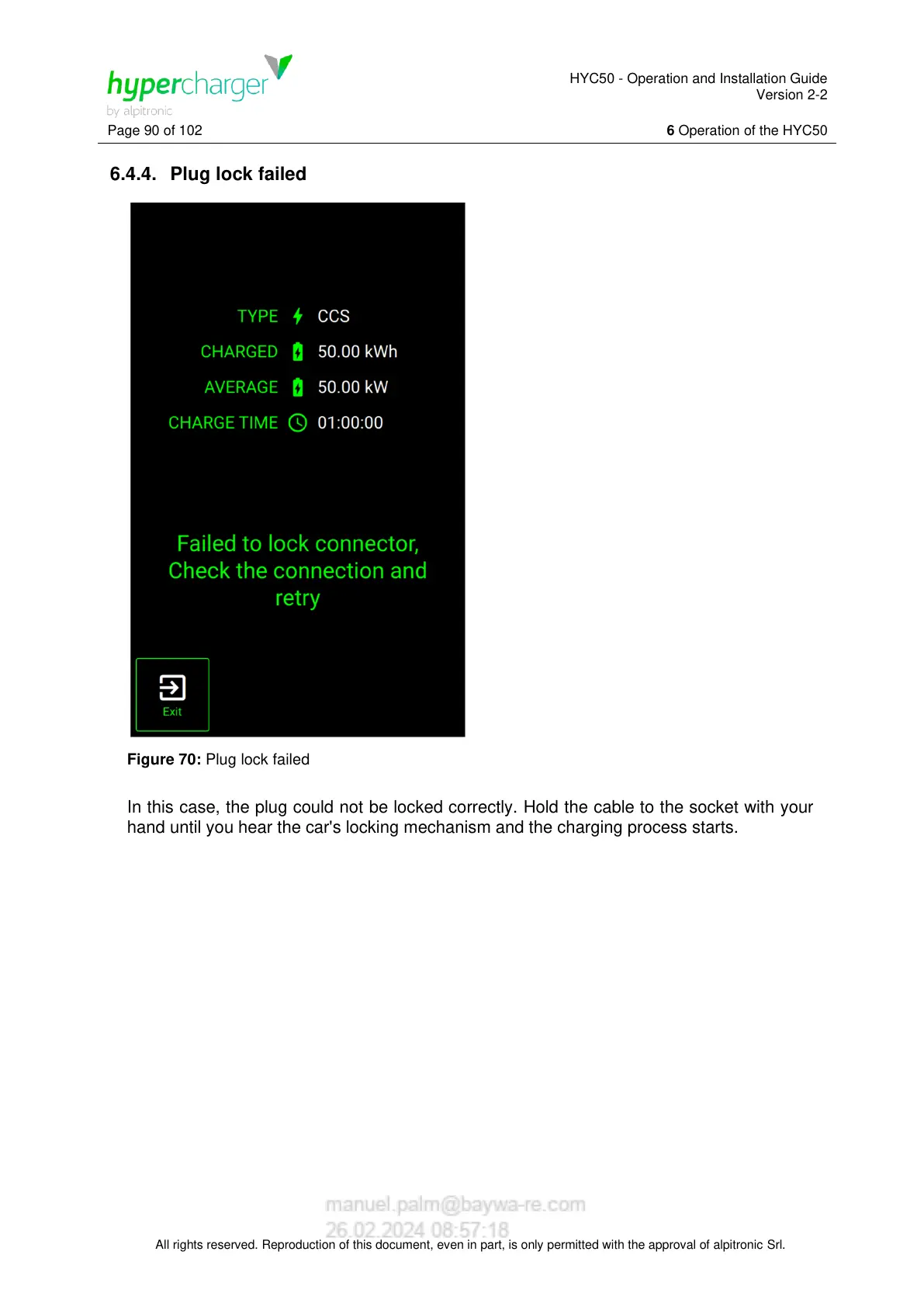
Figure 70: Plug lock failed
In this case, the plug could not be locked correctly. Hold the cable to the socket with your
hand until you hear the car's locking mechanism and the charging process starts.