HYC50 - Operation and Installation Guide
Version 2-2
4 HYC50 installation and commissioning
All rights reserved. Reproduction of this document, even in part, is only permitted with the approval of alpitronic Srl.
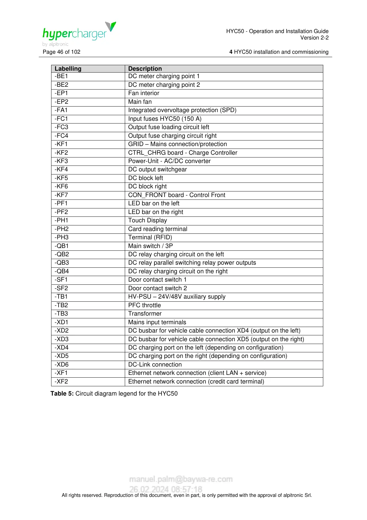
DC meter charging point 1
DC meter charging point 2
Integrated overvoltage protection (SPD)
Input fuses HYC50 (150 A)
Output fuse loading circuit left
Output fuse charging circuit right
GRID – Mains connection/protection
CTRL_CHRG board - Charge Controller
Power-Unit - AC/DC converter
CON_FRONT board - Control Front
DC relay charging circuit on the left
DC relay parallel switching relay power outputs
DC relay charging circuit on the right
HV-PSU – 24V/48V auxiliary supply
DC busbar for vehicle cable connection XD4 (output on the left)
DC busbar for vehicle cable connection XD5 (output on the right)
DC charging port on the left (depending on configuration)
DC charging port on the right (depending on configuration)
Ethernet network connection (client LAN + service)
Ethernet network connection (credit card terminal)
Table 5: Circuit diagram legend for the HYC50
 Loading...