Product Overview and General Specifications
19
Instruction Manual – Enova DGX 8/16/32/64 Digital Media Switchers
The following sections briefly introduce the hardware on the rear of the enclosure.
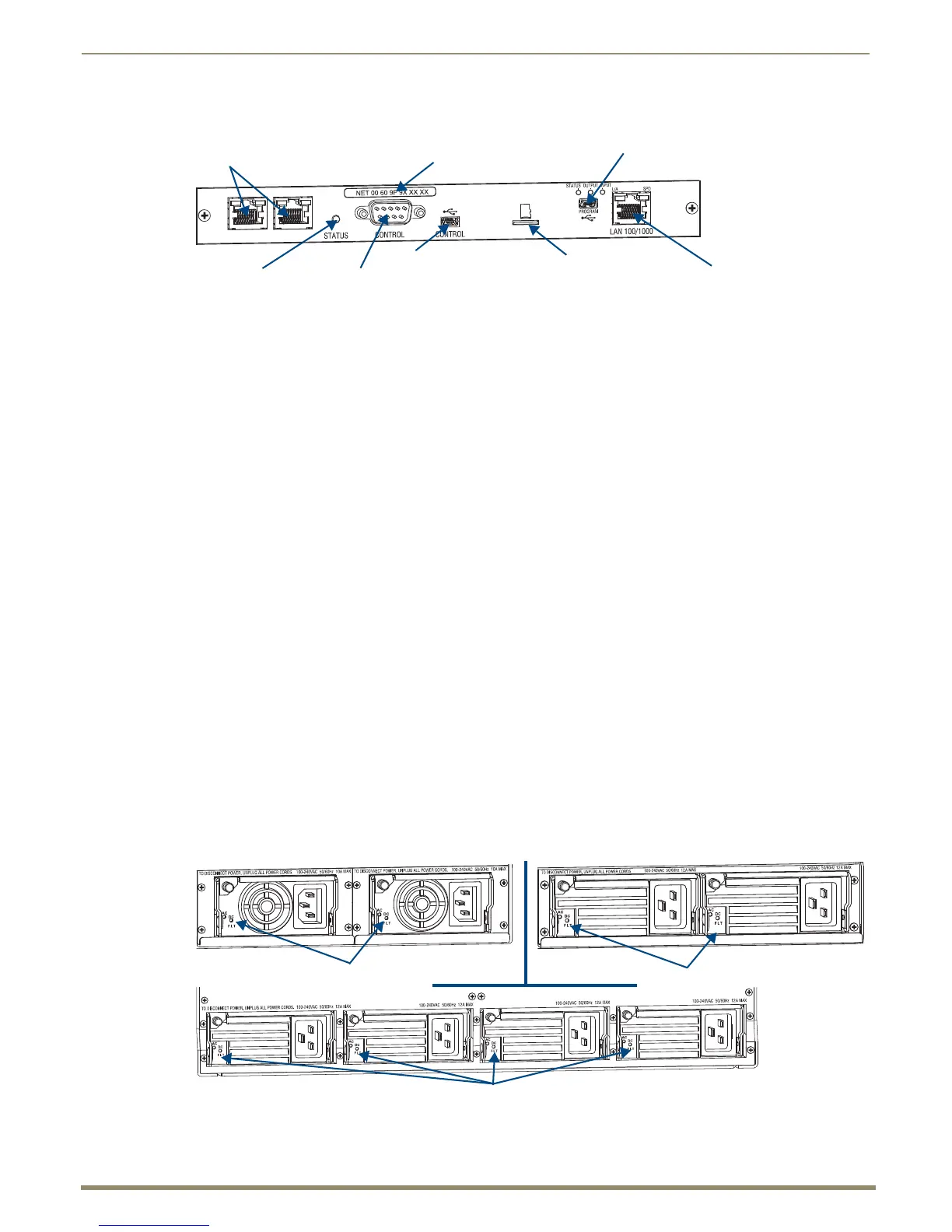
CPU/Control Board
The CPU/Control board is on the left rear of the enclosure, directly below the input connectors.
Each CPU includes the following port and slot options:
Two RJ-45 ports – for connecting autonomous devices (linking of enclosures is not allowed)
Control port* (DB-9, RS-232) – for attaching an external serial control device (see page 59)
Control port* (USB mini-B) – for attaching an external control device (see page 61)
SD card slot – ships with an installed Micro SD memory card for CPU backup (see page 66)
Program port (USB mini-AB) – for establishing a connection from the Integrated NetLinx Master to the PC’s
COM port (see page 47) and for initial setup of the system
LAN 100/1000 port (Ethernet RJ-45) – the connection from the integrated NetLinx Master to a LAN (see
page 47) for all runtime control, NetLinx programming, etc.
Each CPU includes four LED indicators:
System Status LED (to the left of the Control ports) – for system status
Status, Output, and Input LEDs (above Program connector) – indicate system communication status and
when data is sent and received (for modes and blink patterns, see page 47)
* The two Control ports provide direct control of matrix switcher processing (they do not work on the same layer of
control as the integrated Master, which uses the LAN 100/1000 and Program ports).
Power Supply Units
Each of the power supply units on the rear of the enclosure (FIG. 8) has a power receptacle that will accept all major
international standard power sources. (US power cords are included with all shipments unless ordered otherwise.)
Maximum power specifications are provided on the power supply receptacles. For information on applying power, see
page 42.
Each power supply unit has two LED indicators:
AC: Green LED – power is good
DC: The DC indicator uses a tri-color LED
Green – power is good
Amber – temperature is above normal
Red – power supply is in a fault state
FIG. 7 CPU/Control board
FIG. 8 Power supply receptacles for Enova DGX 8/16 (upper left), Enova DGX 32 (upper right), and Enova DGX 64 (below)
Control (USB mini-B) port
RJ-45 ports
Control (DB-9, RS-232 serial) portSystem Status indicator
LAN 100/1000 port
Program (USB mini-AB) port
and LED indicators
SD card slot
MAC address
Enova DGX 8/16 - Indicator LEDs
Enova DGX 32 - Indicator LEDs
Enova DGX 64 - Indicator LEDs
 Loading...