Line buildoutLine buildout
Timing sourceTiming source
FollowsFollows
This screen allows you to make the physical setup of the PDH transmitter in
DS3 mode. It can also be used to inspect the current status of the selected port.
The configuration options available in the setup area of the screen are
described below. The status information is described in Status Summary.
Select the line build-out. The available values are:
High-0 ftHigh-0 ft
DSX-450 ftDSX-450 ft
To set transmission based on ITU-T G.703, select DSX - 450 ftDSX - 450 ft.
Select the clock source.
InternalInternal: Internal clock of the module
ExternalExternal: The clock provided from the Ext Clock connector
ReceivedReceived: The clock generated from the received signal
When ExternalExternal or ReceivedReceived is set, the right hand lamp indicates whether clock
is detected or not.
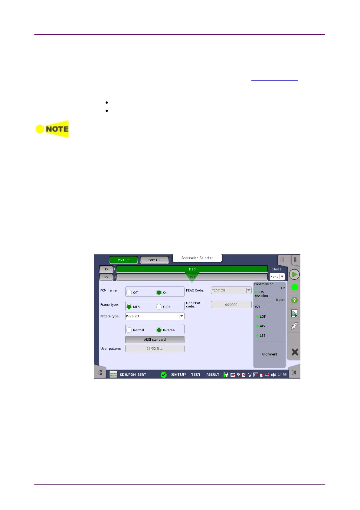
55..66..11..22 DS3 Signal SetupDS3 Signal Setup
Touching the transmitter's DS3DS3 button in the navigation area will display the
screen shown below.
To make the Port 2 transmitter follow the Port 1 transmitter (i.e. copy its
settings) when using Port 1 and Port 2, touch the drop-down menu in the
navigation area and select the Tx1Tx1. The Port 2 settings continue to follow the
Port 1 transmitter change. The default setting is NoneNone. Note that the Port 1
transmitter cannot follow the Port 2 transmitter.
PCM framePCM frame
Use the PCM framePCM frame radio buttons to enable (OnOn) or disable (OffOff) insertion of
PCM frame in the transmitted signal.
Frame typeFrame type