33..33..22 Service InterfacesService Interfaces
The service interfaces used for the connection to other instruments, are placed
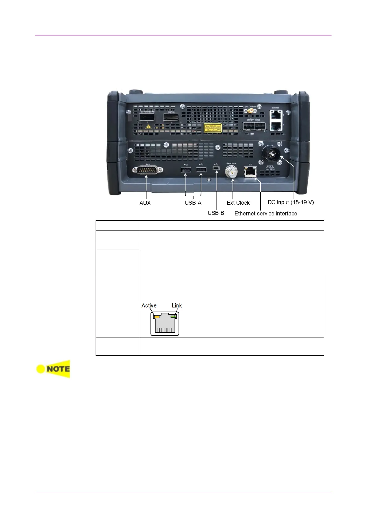
on the MT1040A panel:
AUX The AUX connector is used for optional G0325A GPS Receiver.
Ext Clock Input The Ext Clock Input connector is used for reference clock input.
USB B The three USB connectors (two connectors type A and one
connector type B mini) can, for example, be used for connection
with USB flash drive. This is convenient for the exchanging of
information to other instrument.
USB A
Ethernet
service
interface
The Ethernet connector is used for connecting the Network Master
to a Local Area Network, e.g. to remotely operate the instrument
from a PC.
Active LED turns on orange while data are sent or
received.
Link LED turns on green when Ethernet has been
linked up and is able for the communication.
DC input 18-19
V DC
The DC power connector is used for connection of 19 V DC power
delivered from the AC adapter.
A Network Master supports only USB flash drives formatted in FAT32.
When multiple USB flash drives are connected to the Network Master, only the first
connected USB flash drive is recognized.
For Wi-Fi dongles confirmed to work with the Network Master, please contact
an Anritsu sales office.