SECTION 5 – INSTALLATION INSTRUCTIONS
UL EX3470 ULC EX3470
PAGE 5-14 REV. 11 2014-SEP-01
R-102 Restaurant Fire Suppression Manual
INSTALLING THE DETECTION SYSTEM (Continued)
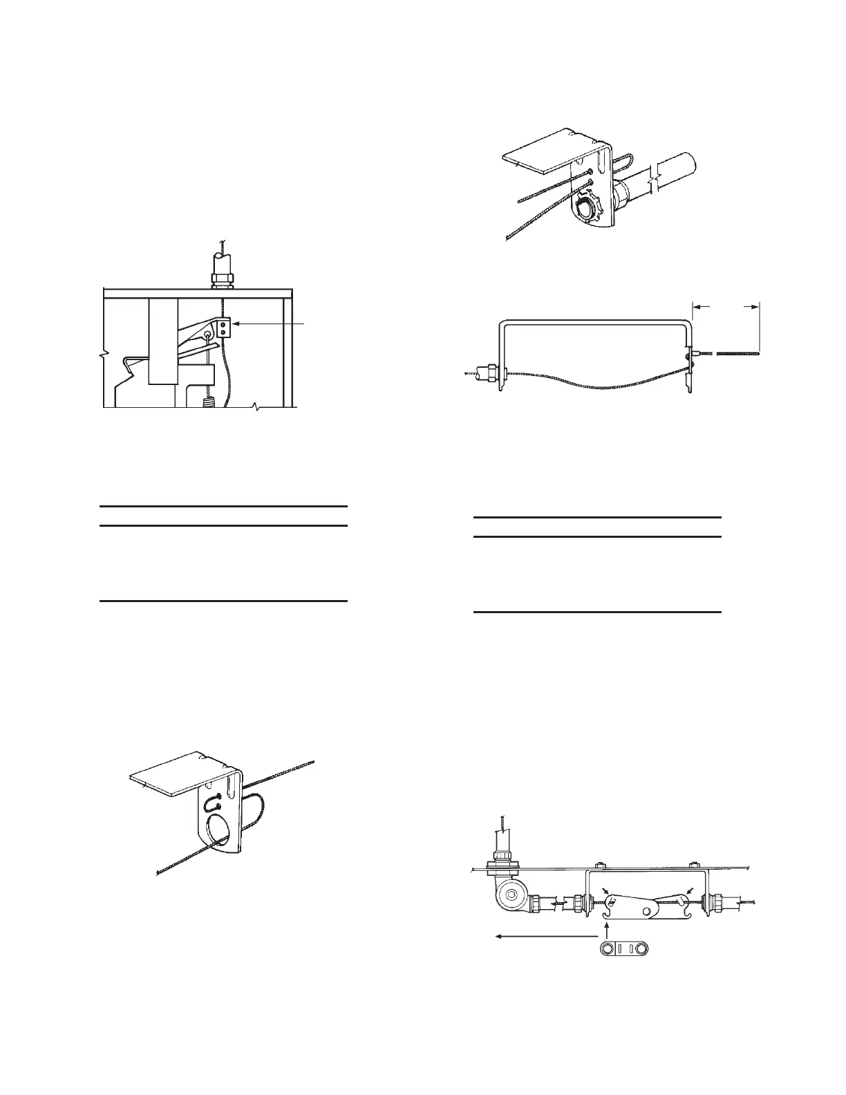
“Scissor” Style Linkage Installation (Continued)
3. Starting at the release assembly, feed the wire rope through
the hole in the release mechanism locking clamp, allowing
the excess wire rope to hang down. (Do not tighten set
screws in locking clamp at this time.) See Figure 5-24.
LOCKING
CLAMP
FIGURE 5-24
000309
4. From the release assembly, run the stainless steel wire rope
through the conduit, pulley elbows and detector brackets to
the terminal detector.
NOTICE
If wire rope requires splicing, make certain
splice is at least 12 in. (305 mm) away from
any pulley elbow or conduit adaptor to avoid
interference.
5. Feed the wire rope through the terminal detector bracket as
shown in Figure 5-25 or as shown in Figure 5-26 if the termi-
nal detector is mounted within a duct or header opening,
and install the stop sleeve approximately 2 to 3 in. (51 to 76
mm) from the end of the wire rope. See Figure 5-27. Use
the National Telephone Supply Company Nicopress Sleeve
Tool (Stock No. 51-C-887) or equal to properly crimp the
stop sleeve.
FIGURE 5-25
000310
FIGURE 5-26
000311
2-3 IN.
(51-76
mm)
FIGURE 5-27
000312
6. To give a constant tension on the wire rope during instal-
lation of the detector linkage, hang a vice grip or other
weighted device on the excess stainless steel wire rope,
leaving an adequate length of spare wire rope between the
locking clamp and the weighted device.
NOTICE
When attaching the weighted device to the
excess wire rope, allow approximately 3 in.
(76 mm) of wire rope for each detector linkage
for proper installation.
Example: If the system has six detectors, there should be
approximately 18 in. (457 mm) of excess wire rope between
the locking clamp and the weighted device, which will be
utilized when the linkage is put in place.
7. Install detector scissor assembly as shown in Figure
5-28. Note that the AUTOMAN release or remote release
assembly is located on the left side of the detector bracket.
Slightly crimp the two assembly “boot-hooks” over the
cable with pliers so the cable is captured under each hook
but the whole assembly can move from side to side. Center
the assembly in the detector bracket.
FIGURE 5-28
000503
AUTOMAN RELEASE OR
REMOTE RELEASE ASSEMBLY
 Loading...
