SECTION 5 – INSTALLATION INSTRUCTIONS
UL EX3470 ULC EX3470
2014-SEP-01 REV. 11 PAGE 5-15
R-102 Restaurant Fire Suppression Manual
INSTALLING THE DETECTION SYSTEM (Continued)
“Scissor” Style Linkage Installation (Continued)
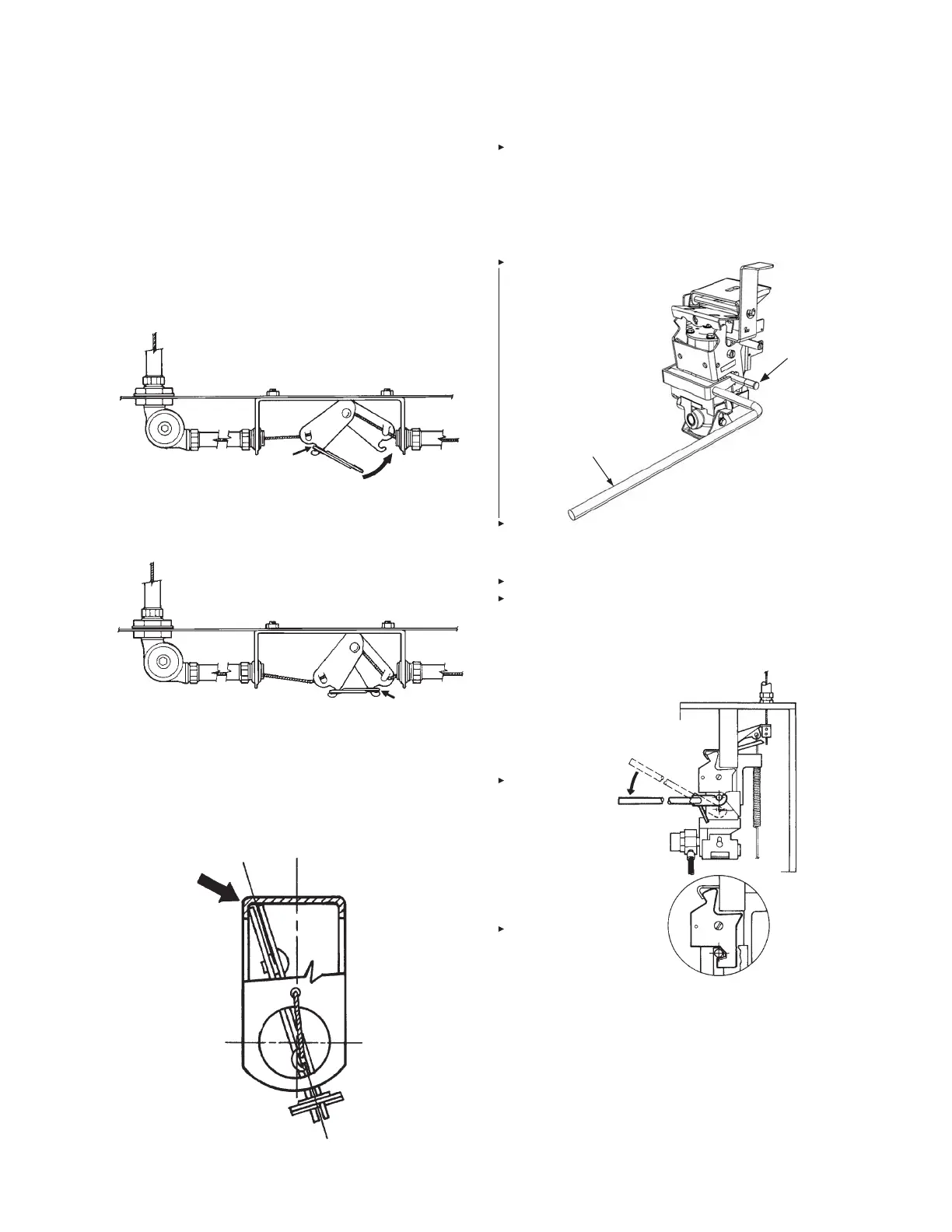
8. Hook the fusible link on the AUTOMAN release or remote
release assembly side of the hook assembly, then pull the
fusible link to the opposite side and complete the hookup
as shown in Figures 5-29 and 5-30. The top of the hook
assembly must be inside the bracket stiffeners. The hook
assembly with the ANSUL fusible link in place must be
located toward the terminal detector side of the bracket.
FIGURE 5-29
000504
FIGURE 5-30
000324
9. Install the linkage and the correct ANSUL approved fusible
link in the remainder of the detector brackets. Make certain
all detector linkages are positioned against either the front
or back upper lip of the formed detector bracket. See Figure
5-31.
FIGURE 5-31
004429
10. Insert cocking lever (Part No. 441042 or Part No. 441041)
on left side of the release mechanism, with the movable
flange resting securely against the corner of the cartridge
receiver and spring housing, and with the notched lever
portion engaging the cocking pin on both sides of the
release mechanism. See Figure 5-32.
COCKING LEVER
COCKING PIN
FIGURE 5-32
009461
11. Using long handle cocking lever (Part No. 441041) or
wrench on short handle cocking lever (Part No. 441042),
pull down to raise cocking pin until the trip lever indented
surface moves underneath the pin and locks the pin in the
up position. See Figure 5-33.
FIGURE 5-33
000320
 Loading...
