SW Version 2.04 30-January-2009 Page 22 of 128
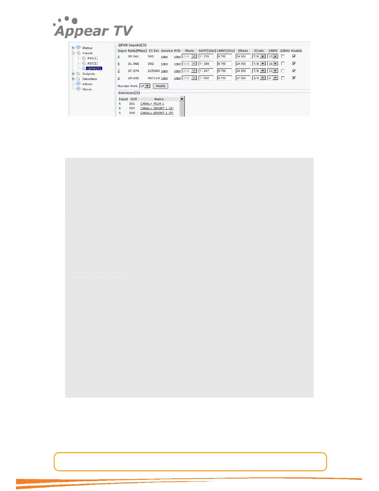
Figure 11 - QPSK input
The QPSK input window shows all configurable settings as well as the current bit rate
and service information. The following parameters are available:
Port Shows the port on the QPSK input module
Rate[Mbps] Shows the incoming data rate
CC Err Bit Error Rate is a quality indication of the input signal.
Incorrect configuration of the transponder parameters will
display no sync.
Service Filtering of the displayed service information. When selected,
only the services available from the selected input port are
displayed under Services.
PID Packet Identifier. When selected, all available PIDs from the
selected input port are displayed instead of the service list.
Mode Switch between DVB and MPEG mode. Default is DVB. Please
use the MPEG mode if the incoming transport stream is not
DVB compliant.
SATF[GHz] Satellite Frequency. Set the satellite transponder frequency.
LNBF[GHz] Low Noise Block Frequency. Set the L
SRate Symbol Rate. Set the symbol rate of the incoming QPSK
signal. The valid range is 1
ICode Inner Code. Set the FEC overhead fraction. E.g. ¾.
LNBV Low Noise Block Voltage. Switch between 0V, 13V or 18V.
22 kHz Switch On/Off the 22kHz output signal
Enable Enable the corresponding input port
To monitor any of the demodulated QPSK input signals, one of the QPSK input ports
can be assigned to the output ASI monitor interface. The demodulated QPSK input
signal will then be copied onto the monitor port for further analyzing or monitoring of
the transport stream. Normal operation will not be affected by using the monitoring
port.
Save the settings by clicking the Apply button