SW Version 2.04 30-January-2009 Page 91 of 128
redundancy implemented, the network should automatically switch to the spare
source.
In order for the network to understand that two multicasts are the same, both the
source and destinations IP address need to be the identical. This is important and
must be taken care of during configuration of the unit.
4.7.5.2 Multicast Configuration
Each subnet must have a designated PIM router (PIM DR). By default, the router is
the DR. But when output redundancy is enabled, the IP output card takes over the
role as the sub network’s DR. All multicasts with different IP addresses than the
multicasts from the IP output cards are stopped by the router. Hence, all IP output
cards must have a separate subnet.
The configuration of these source addresses is a two step process. The first step is to
define which network subnet to use as the source address. The second step is to
specify the unique source for the actual multicast.
4.7.5.3 OSPF Configuration
OSPF is used to configure the routers. The routing decision is made on every step in
the path. The choice is based on the metric. The metric is based on the number of
hops taken and the cost added manually. The redundancy scheme does currently not
support any other routing protocols.
4.7.5.4 Defining the Source Subnet
In the context of IP output redundancy the source subnet refers to the network
segment which is to be used as the source network. This network needs to be the
same for both output cards, which shall be configured as redundant to each other.
The source subnet is a network parameter that is applicable to each output card.
Therefore it is configured as part of the IP address setup for each output card on the
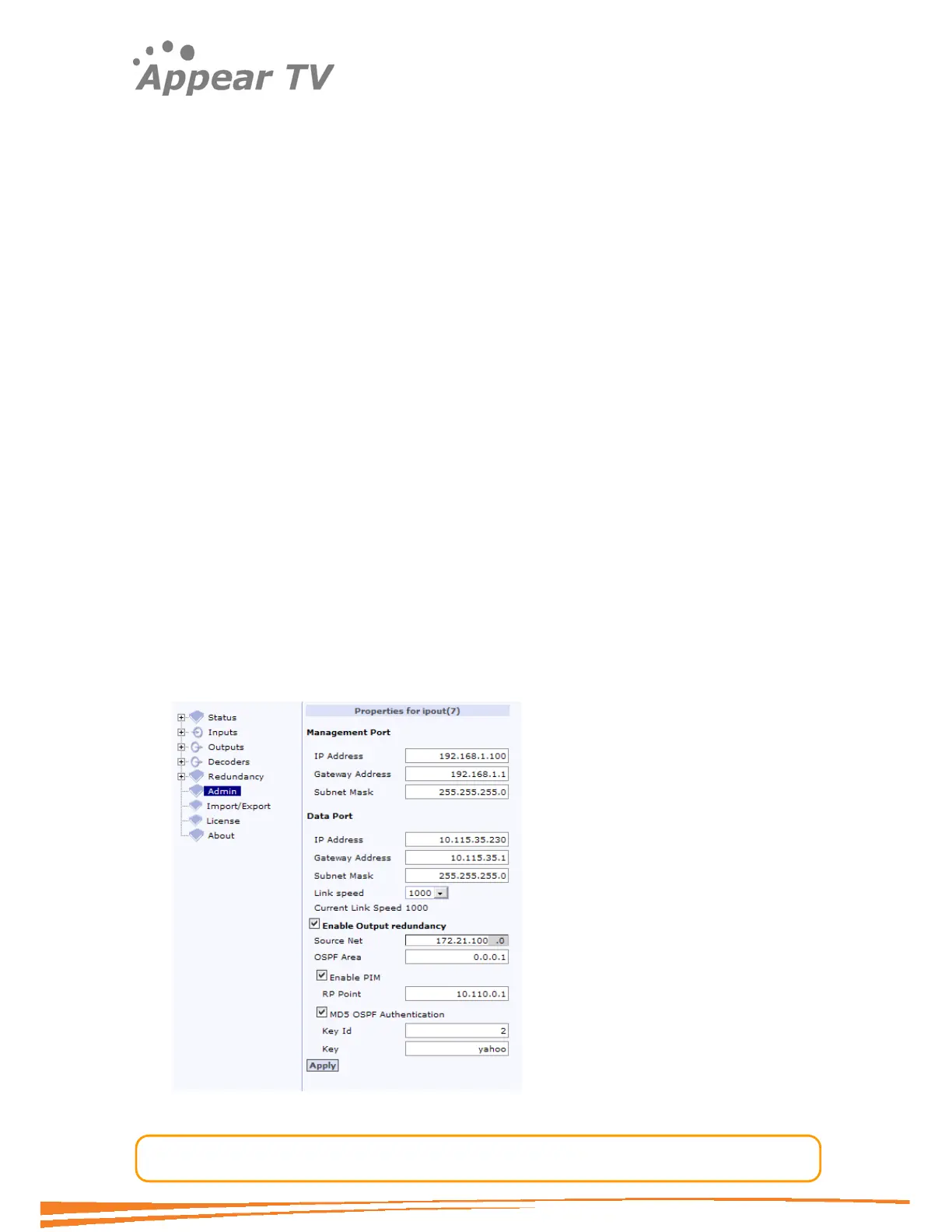
ipout page. Go to the Admin node in the navigation tree and click on the IP output
card to be configured. This will open the ipout page displayed in Figure 51 below.