EasyManua.ls Logo

Applied Systems Engineering ASE2000 User Manual

Default Icon
219 pages
To Next Page IconTo Next Page
To Previous Page IconTo Previous Page
Page #146 background image
ASE2000 V2 Communication Test Set User Manual 146
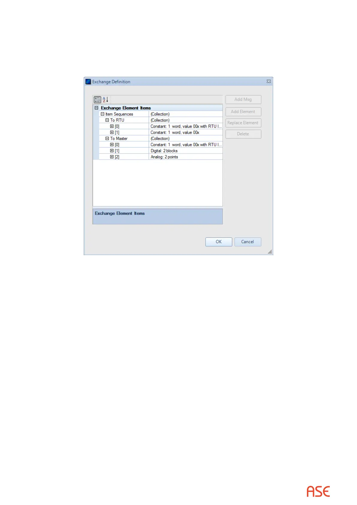
From the Exchange view, right-click on the line containing the Scan exchange and select
Edit Exchange Denition. Under the “To Master” section, select the element “Points: Digital:
2 blocks”, select “Add Element”, select “Analog”, then OK. Expand the updated element and
change the repeat count to 7. This indicates 7 “blocks” of Analog points, one point per block.
Conitel documetion refers these “blocks” as sections. Click OK.
The modied Exchange Denition for 24 Digital and 7 Analog points is shown above.
25.1.2. Conitel – Exchange Mode Set RTU ID and Group
The RTU ID and Group number can be set for all exchanges from the Protocol > Properties
display or individually on the Exchange List view.
25.1.3. Conitel – Exchange Mode Line Monitor
No additional setup is required. If cabling is correct Line Monitoring can be started by selecting
the Start button.
25.1.4. Conitel – Exchange Mode Master Simulation
If the Communication Properties, Exchange Denition, RTU ID, and Group number have been
congured, Master Simulation operations can be performed. No additional setup is required.
25.1.5. Conitel – Exchange Mode RTU Simulation
If the Communication Properties, Exchange Denition, RTU ID, and Group number have been
congured, RTU Simulation operations can be performed. No additional setup is required.

Table of Contents

Question and Answer IconNeed help?

Do you have a question about the Applied Systems Engineering ASE2000 and is the answer not in the manual?

Applied Systems Engineering ASE2000 Specifications

General IconGeneral
BrandApplied Systems Engineering
ModelASE2000
CategoryMeasuring Instruments
LanguageEnglish

Summary

1. Overview

Line Monitor Mode

Provides visibility into communication between master and remote devices.

Master Simulation Mode

Simulates a master to exercise and diagnose remote devices.

RTU Simulation Mode

Simulates remote devices to exercise the master.

2. Version 1 / Version 2 Comparison

Exchange Mode vs Task Mode Highlights

Highlights the primary differences between Exchange and Task operational modes.

Operational Basics

Details the operational basics of Exchange and Task modes.

3. Software Installation

Hardware Requirements

Details required hardware for ASE2000 Version 2 operation.

Installation Procedure

Outlines the step-by-step procedure to install ASE2000 Version 2.

4. Quick-Start Guide

Select Operational Mode

Explains how to select between Task and Exchange operational modes.

Protocol Selection and Configuration

Details how to select and configure the communication protocol.

Communication Settings

Describes setting communication parameters for serial and network connections.

4.7. Select Communication Mode and Start Communicating

Master Simulation Mode Selection

Explains selecting Master Simulation mode via icons.

Task Mode Operation Steps

Explains processing tasks in different modes.

5. File Types

File Type Descriptions

Describes various file types used by ASE2000 V2.

6. Communication Message Processing

Message Export/Import Facility

Explains saving and retrieving message data using MSGX files.

Message Capture Facility

Explains saving message data using a capture database.

7. Screen Layout

Menu Bar and File Menu

Describes the menus and items within the File pull-down menu.

Tool Bar Overview

Describes the Tool Bar and its player buttons.

Status Line and Statistics

Describes the status line and communication statistics.

8. View Menu Details

Point List View

Describes the display of input points detected on the communication line.

Exchange List View

Describes the Exchange List view in Exchange Mode.

8.4. Line Monitor View

Edit Menu for Line Monitor View

Details the Edit Menu options for the Line Monitor view.

Raw Text Export

Explains exporting raw data from the line monitor to a text file.

8.7. Line Analyzer

Edit Menu for Line Analyzer View

Details the Edit Menu options for the Line Analyzer view.

9. Exchange Mode

Starting Communication

Details how to start communication in Exchange Mode.

Master Simulation Operations

Describes starting Master Simulation targets.

10. Task Mode

Device Definition

Guides on defining devices in the Task Mode database.

Task Mode Operation, Master Simulation Mode

Explains Master Simulation operation within Task Mode.

Task Mode Operation, RTU Simulation Mode

Explains RTU Simulation in Task Mode.

13. ASE2000 Cabling

RS-232 Connections

Illustrates cabling configurations at the RS-232 level.

Modem Connections

Illustrates cabling configurations through a modem.

14. ASE2000 Network Protocol Use

Master Mode Network Operation

Explains operating as a Master and configuring IP/device addresses.

Monitor Mode Network Operation

Explains monitoring network messages between devices.

15. ASE2000 V2 Command Line Options

Command Line Option Usage

Lists and explains command line options for ASE2000 V2.

16. ASE BELL-202 Dual-Channel Modem Adjustment

White Potentiometer Adjustments

Details adjustments for modems with white colored potentiometers.

Orange/Yellow Potentiometer Adjustments

Details adjustments for modems with orange/yellow potentiometers.

17. RS-232 Cable And Adapter Pin-Out

DB-25 Connector Pin-Out

Provides the pin-out for DB-25 connectors.

DB-9 Connector Pin-Out

Provides the pin-out for DB-9 connectors.

18. ASE2000 Kit Contents

Model ASE2000-USB-M Contents

Lists the components included with the ASE2000-USB-M model.

20. BCOM-USB Device Guide

BCOM-USB Overview

Provides an overview of the BCOM-USB 2-channel serial RS-232 device.

BCOM-USB I/O Driver Installation

Describes steps to install the BCOM-USB device I/O drivers.

21. BCOM-USB Windows 7 and Windows 8 I/O Driver Installation

Driver Installation Steps

Provides driver installation instructions for Windows 7 and 8.

21.1. BCOM-USB device Troubleshooting

BCOM-USB I/O Driver Communication Problems

Details verifying BCOM-USB communication.

22. ASE License/Firmware Updater

Updater Overview and Operation

Explains the updater program and its operation.

License and Firmware Installation

Guides on installing new license files or firmware.

23. CDC Type I – Protocol Specific

CDC Type I – Exchange Mode

Covers editing Exchange Definition and RTU address for CDC Type I.

CDC Type I – Task Mode

Covers Task Mode setup for CDC Type I.

26. DNP3 – Protocol Specific

DNP3 – Exchange Properties Menu

Describes the Exchange Properties Menu for DNP3.

DNP3 Simulation Sub-Tab

Details DNP3 RTU and Master Simulation properties in Task Mode.

DNP3 Secure Authentication Setup

Explains enabling and configuring DNP3 Secure Authentication.

27. Harris 5k/6k – Protocol Specific

Harris 5k/6k – Exchange Mode

Covers editing Exchange Definition for Harris 5k/6k.

Harris 5k/6k – Task Mode

Covers Task Mode setup for Harris 5k/6k.

28. IEC 60870-5 – Protocol Specific

IEC 60870-5 – Exchange Properties Menu

Describes the Exchange Properties Menu for IEC 60870-5.

IEC 60870-5 – Task Mode

Covers Task Mode setup for IEC 60870-5.

29. Modbus – Protocol Specific

Modbus – Exchange Mode

Covers editing Exchange Definition and RTU address for Modbus.

Modbus – Task Mode

Covers Task Mode setup for Modbus.

30. Telegyr 8979 – Protocol Specific

Telegyr 8979 – Exchange Mode

Covers editing Exchange Definition and RTU address for Telegyr 8979.

Telegyr 8979 – Task Mode

Covers Task Mode setup for Telegyr 8979.

Related product manuals