ASE2000 V2 Communication Test Set User Manual 166
Process IIN – If enabled, this feature will send messages to the RTU Id selected above in
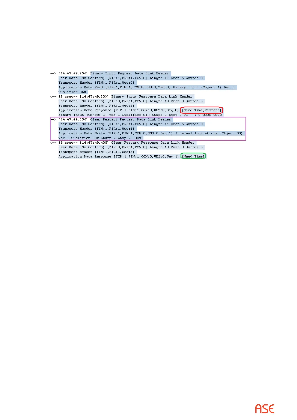
response to Internal Indications ags appearing in responses from the RTU. In the example
below, the RTU response to a Binary Input Request contains IIN ags for Need Time and Restart.
The ASE2000 rst forms a Clear Restart Request and sends it to the RTU. In the Clear Restart
Response, the Restart indication has been cleared. This will be followed by a sequence to
measure the response delay and write a synchronized date & time to the RTU (not shown).
Disable UDP Listen during Master Simulation – This option is only needed when multiple
copies of the Test Set are running on the same machine. When running in Master Simulation,
the Test Set listens on the UDP port for unsolicited messages from the RTU. In RTU simulation,
the Test Set also listens on the UDP port for incoming messages from the Master station. Since
two copies of the application cannot both be listening to the same port, the instance running in
Master Simulation mode will not listen on the UDP port when this option is selected.
26.4.3. DNP3 – Mapping Output Controls to Change Input Point Values
To modify values at the RTU by sending controls from the master station, select this feature from
the RTU Simulation sub-tab in the Properties menu. A Trip command defaults to a value of zero
and a Close command defaults to one. To invert this interpretation, select the ‘Invert Trip/Close
Value’ check box.
Add the control point Id enclosed in square brackets to the description eld of the input point to
create the link. The mapping value may appear anywhere in the description eld. It is a one-way
link. Individual points may be inverted by prexing the point ID with an exclamation point such
as [!23]. To change digitals using two controls, specify both controls separated by a colon as
[zero:one]. For example, [3:5], which will set the point value to 0 when operating control point 3
and set the value to 1 when any control operation to control point 5 is received.
Binarylink– [101]appearsinthe DescriptioneldforPoint DI201: Write commands to
point DOs 101 change the value of DI 201
Dual control binary link – [104:107] for Point DI 203: Write zero to DI 203 when operates to
DOs 104 are received; write one to DI 203 when operates to DOs 107
Negated binary link – [!105] appears in the Description eld for Point DI 205: Write
commands to DOs 105 change the value of DI 205 to the opposite value
Analoglink–[10]appearsintheDescriptioneldforPointAI22: A value written to point
AOs 10 will be set as the value of AI 22