ASE2000 V2 Communication Test Set User Manual 177
The following rules explain how responses are generated from the table below. Point modeling
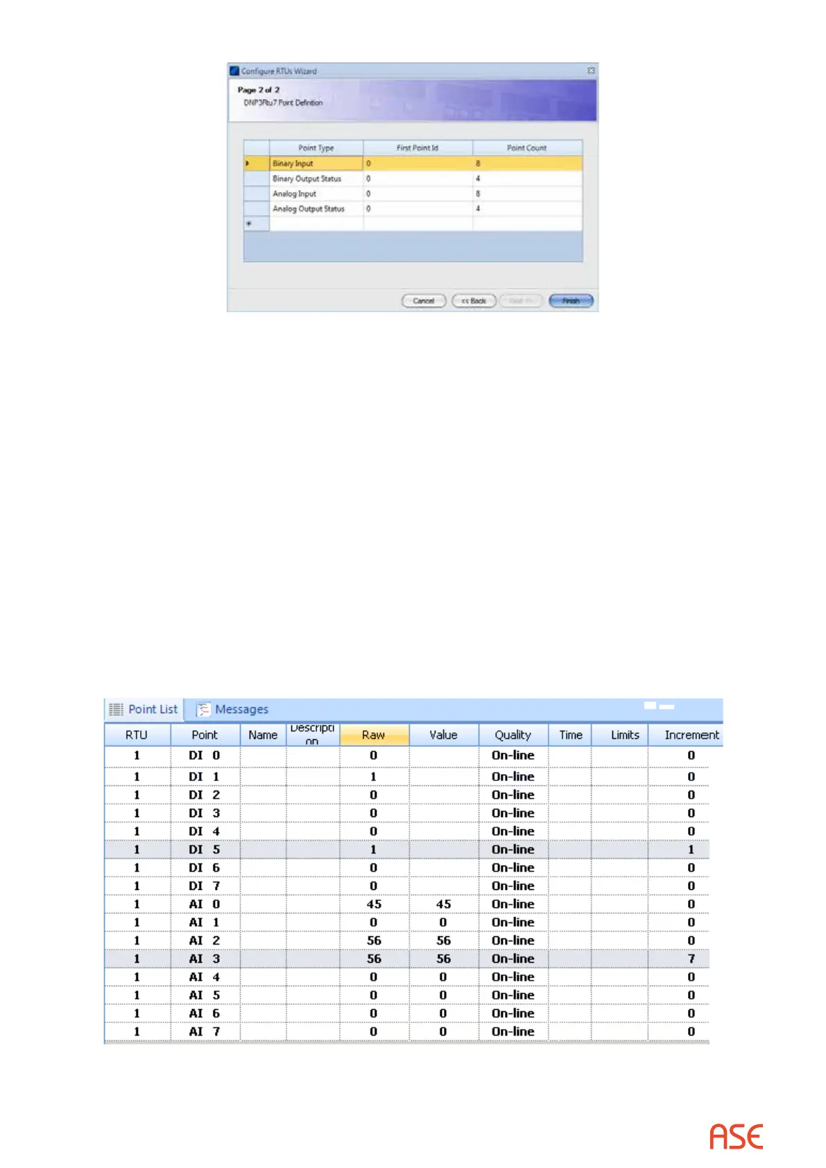
is the ability to specify point value changes and is supported by performing data entry in the Raw
and Increment columns.
• Static objects are always sent with a variation that includes ag (quality code) information
• Event objects are always sent with time
• The Raw column contains the last value sent for the corresponding point/object. A value shown
in normal video has already been transmitted. A new value can be entered. It appears dim until
sent, after which it is redisplayed in normal video
• For Binary points, an event is generated on the scan following entry of a new Raw value
• Binary points can be congured to change in every scan response by entering a 1 in the
Increment column. Each response will then include an event with a state dierent from the
prior response
• Analog points can be congured to change in every scan response by entering a non-zero
value in the Increment column. Each response will then include a value that will dier from
the previously transmitted value by the increment amount. Over time, values will ramp up and
down between high and low limits. A new analog value generated due to a non-zero increment
is reported as an analog change event