ASE2000 V2 Communication Test Set User Manual 22
Verify current settings and, where appropriate, modify the settings for the current test session.
NOTE: If a switch to a dierent Operational Mode is performed after modication of a communication
setting, re-check the settings as they may have changed as a result of the mode switch.
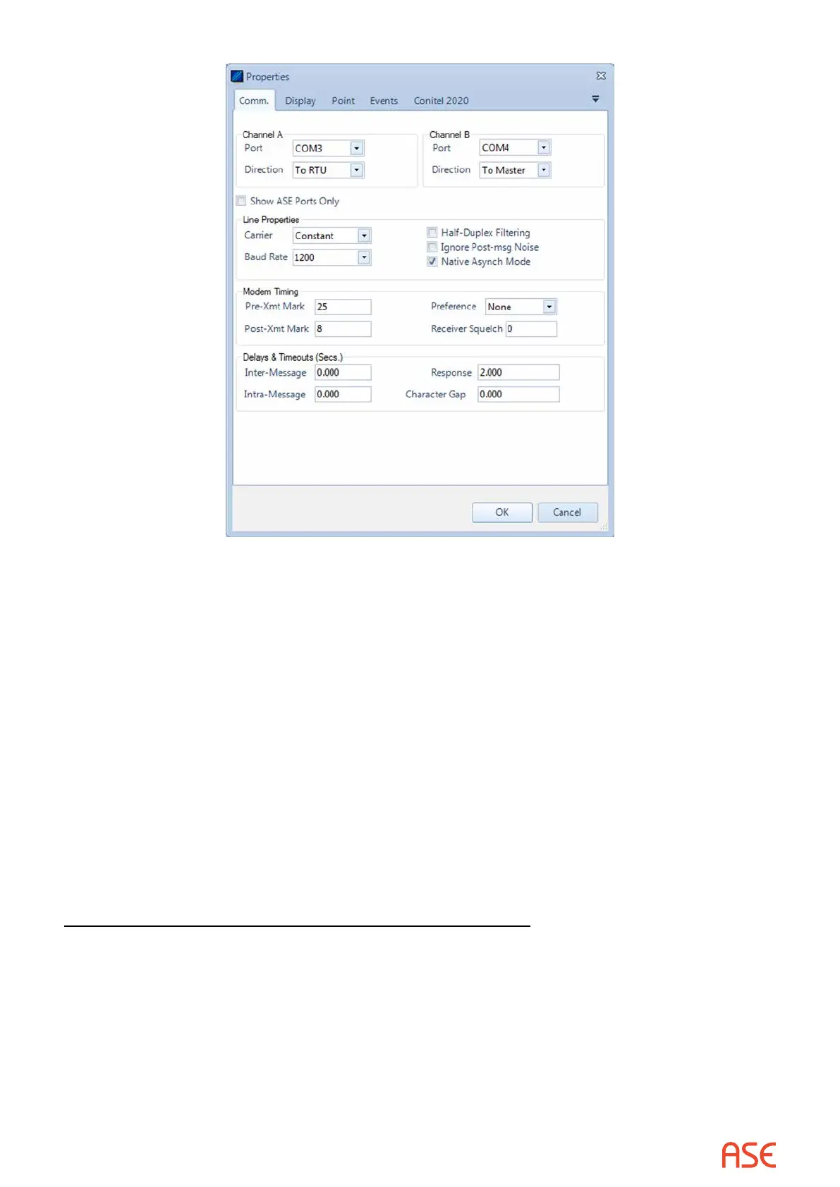
1. Verify the Channel A and Channel B Direction settings reect the physical connection
between the test set PC and equipment being tested. If working in Master Simulation or RTU
Simulation mode, only one channel connection is necessary.
2. Under Line Properties, set Carrier setting. In most cases, Switched or Constant will be used.
If the physical connection utilizes a Null Modem or a real modem, the setting should be
Switched. Otherwise, use Constant. For the other settings, see the more detailed description
of the communication settings.
3. Verify Baud Rate matches baud rate of device to be communicated with.
4. If the selected protocol is byte-oriented, check the “Native Async Mode” check box. For bit-
oriented protocols, un-check it.
5. The default Modem Timing settings will usually work in most circumstances.
6. The default Delays & Timeouts will usually work in most circumstances.
Communication Settings for Network Communication
Conguration of communication settings for network communications utilizes the Properties
display and the “protocol specic” tab (DNP3 WAN/LAN, Modbus TCP, or IEC 60870-5-104).
From the main task bar, select Tools > Properties > “protocol specic” tab. In most cases, the
default parameters will be sucient. For Master Mode, it is necessary to enter the IP address
of the Slave device. This is entered in the Host eld. For RTU Simulation and Monitor Mode
it is not necessary to enter an IP address. Select IPv6 when monitoring devices or providing
Host addresses using the broader IPv6 address space. (Other options are protocol specic and
described in their respective sections.)