EasyManua.ls Logo

Aspen Avionics EFD1000 E5 User Manual

Aspen Avionics EFD1000 E5
226 pages
To Next Page IconTo Next Page
Page #1 background imageLoading...
Page #1 background image
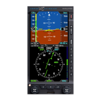
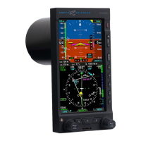
EFD1000 E5 Dual Electronic Flight Instrument (EFI) Install Manual
DOCUMENT # 900-00041-001 PAGE 1-226 REVISION D
© Copyright 2019 Aspen Avionics Inc.
EFD1000 E5
Dual Electronic Flight Instrument (EFI)
Installation Manual
April 2019

Table of Contents

Questions and Answers:

Aspen Avionics EFD1000 E5 Specifications

General IconGeneral
Display TypeActive Matrix LCD
Resolution1024 x 768 pixels
Weight3.3 lbs (1.5 kg)
Operating Temperature-15°C to +55°C
Display Size6.25 in. diagonal
InterfacesRS-232, ARINC 429

Summary

EFD1000 E5 Dual Electronic Flight Instrument (EFI) Install Manual

Special Notes to the Installer

1 Introduction

1.1 Part Numbers

List of major hardware components (by part number) that make up the EFD1000 E5 system.

1.1.1 Latest Approved Software Versions

Details of the latest approved software versions for EFD1000 E5 components.

1.1.2 AML-STC Document List

List of documents containing engineering aspects part of AML-STC SA10822SC.

1.2 Installation Kit Contents

Details the components included in the EFD1000 E5 basic installation kit.

1.3 Optional LRU Install Kits

Lists optional installation kits for Line Replaceable Units (LRUs) such as ACU and EA100.

1.4 Accessories Required but Not Supplied – EFD1000 E5

Lists accessories that are required for EFD1000 E5 installation but not supplied.

1.5 Optional Accessories Not Supplied – EFD1000 E5

Lists optional accessories for the EFD1000 E5 that are not supplied with the unit.

1.6 Optional Accessories Required but Not Supplied – EA100

Lists optional accessories required for the EA100 adapter installation but not supplied.

1.7 Special Tools Required

Lists specialized tools required for the installation process.

1.8 Vendor Information

Information on suppliers for parts and cables.

1.10 Regulatory Compliance

Details regulatory compliance aspects including TSO and PMA approvals.

1.10.1 Technical Standard Order

Details TSOA authorization for system components.

1.10.2 PMA Approval

Details PMA approval for the EFD component.

1.10.3 Software Certification

Details the system level verification for software approval.

1.10.4 Environmental Compliance

Confirms system components meet environmental test requirements.

1.10.5 Installation Approval

Details FAA approval for EFD1000 E5 installation under AML STC SA10822SC.

1.11 Field Replaceable Parts

Refers to Appendix D and ICA for a list of field replaceable parts.

2 Equipment Specifications and Limitations

2.1 EFD1000 E5

Details specifications for the EFD1000 E5 unit.

2.1.1 General Specifications

Lists general physical and electrical specifications for the EFD1000 E5.

2.1.2 Operational Specifications

Details operational parameters like temperature, humidity, and input voltage.

2.1.3 I/O Specifications

Lists input/output interface capabilities for the EFD1000 E5.

2.1.4 Certification Specifications

Specifies the certification standards met by the EFD1000 E5.

2.1.5 EFD1000 E5 Outline Drawing

Provides dimensional drawings for the EFD1000 E5 unit.

2.1.6 Design Eye Viewing Envelope

Defines the acceptable viewing angles and distances for the EFD1000 E5 display.

2.2 Remote Sensor Module (RSM)

Details specifications for the Remote Sensor Module (RSM).

2.2.1 General Specifications

Lists general physical and operational specifications for the RSM.

2.2.2 Operational Specifications

Details operational parameters for the RSM.

2.2.5 Outline Drawing

Provides dimensional drawings for the RSM unit.

2.3 Configuration Module (CM)

Details specifications for the Configuration Module (CM).

2.3.1 General Specifications

Lists general physical specifications for the Configuration Module.

2.3.2 Operational Specifications

Details operational parameters for the Configuration Module.

2.3.3 I/O Specifications

Lists I/O capabilities for the Configuration Module.

2.3.4 Certification Specifications

Specifies the certification standards met by the Configuration Module.

2.4 Analog Converter Unit (ACU)

Details specifications for the Analog Converter Unit (ACU).

2.4.1 General Specifications

Lists general physical and operational specifications for the ACU.

2.4.2 Operational Specifications

Details operational parameters for the ACU.

2.4.3 I/O Specifications

Lists I/O capabilities for the ACU.

2.4.4 Certification Specifications

Specifies the certification standards met by the ACU.

2.4.5 Outline Drawing

Provides dimensional drawings for the ACU unit.

2.5 Analog Converter Unit 2

Details specifications for the Analog Converter Unit 2 (ACU2).

2.5.1 General Specifications

Lists general physical and operational specifications for the ACU2.

2.5.2 Operational Specifications

Details operational parameters for the ACU2.

2.5.3 I/O Specifications

Lists I/O capabilities for the ACU2 unit.

2.5.4 Certification Specifications

Specifies the certification standards met by the ACU2 unit.

2.5.5 Outline Drawing

Provides dimensional drawings for the ACU2 unit.

3 System Description

3.1 EFD1000 E5 Dual Electronic Flight Instrument (EFI) system

Describes the EFD1000 E5 system architecture and its primary functions.

3.2 EFD1000 E5 Flight Display (EFD)

Details the EFD1000 E5 flight display unit, its components, and mounting.

3.3 Remote Sensor Module (RSM)

Describes the Remote Sensor Module (RSM), its function, and mounting considerations.

3.4 Configuration Module (CM)

Explains the role of the Configuration Module (CM) in system setup.

3.5 Analog Converter Unit (ACU)

Details the function and requirements for the Analog Converter Unit (ACU).

3.6 Analog Converter Unit 2 (ACU2)

Describes the features and capabilities of the Analog Converter Unit 2 (ACU2).

3.7 System Architecture

Illustrates the system architecture showing component relationships.

4 STC Specific Requirements and Limitations

4.1 EFD1000 E5 System Limitations

Specifies limitations for installing the EFD1000 E5 system.

4.2 EA100 Installation Limitations (EA100 is optional)

Details installation limitations for the optional EA100 adapter.

4.3 Authorized Configurations

Lists the authorized configurations for the Aspen EFD1000 E5.

4.4 General Standby Instrument Requirements for IFR-Capable Airplanes

Details standby instrument requirements for IFR-capable aircraft.

4.4.1 Pneumatic Attitude (existing)

Discusses requirements for existing pneumatic attitude indicators.

4.4.2 Electric Attitude (existing)

Discusses requirements for existing electric attitude indicators.

4.4.4 Airspeed and Altimeter

Specifies requirements for existing airspeed and altimeter instruments.

4.4.5 Back Up Nav Indicator

Details requirements for a backup navigation indicator for IFR certification.

4.4.6 Placards

Specifies placard requirements and placement near the EFD1000 E5.

4.5 Special Consideration for Airplanes Limited to VFR

Provides specific requirements for installing the EFD1000 E5 in VFR-limited aircraft.

5 Pre-Modification Planning

5.1 Pre-Modification Checklist

Provides a checklist to ensure aircraft suitability for EFD1000 E5 installation.

5.1.1 Directional Gyro/ HSI

Discusses replacement of Directional Gyro or HSI and associated wiring.

5.1.2 Aircraft Power Requirements

Details aircraft electrical load analysis and EFD1000 E5 power requirements.

5.1.3 Equipment Power Requirements

Specifies power requirements for EFD and ACU/ACU2 installations.

5.1.5 Cessna 190/195 Special Consideration

Addresses specific installation considerations for Cessna 190/195 aircraft.

5.3 Conventional Landing Gear “tail dragger” Aircraft

Provides precautions for installing EFD1000 E5 in conventional landing gear aircraft.

5.4 Optional Interfaces

Details optional interfaces and compatibility with other avionics systems.

5.4.1 Autopilot

Describes autopilot interface requirements and compatibility.

5.4.1.1 EA100 Adapter

Details EA100 adapter installation eligibility and autopilot compatibility.

5.4.2 GPS Navigator Compatibility

Lists authorized GPS navigators and their connection types to the EFD1000 E5.

5.4.3 GPSS

Explains GPSS steering command capability via EFD1000 E5.

5.4.4 GPS/ NAV Switching

Describes removal of existing GPS/NAV switching and EFD1000 E5 capability.

5.4.5 Heading Output

Details the available formats and sources for heading output.

5.4.6 Air Data Outputs

Lists the available formats for air data output from the EFD1000 E5.

5.4.6.1 EFD1000 E5 as Encoding Altitude Source

Explains how the EFD1000 E5 can be used as an encoding altitude source.

5.4.7 Flush or Recess Mounting the EFD

Provides instructions for flush or recess mounting the EFD display.

6 Mechanical Installation

6.1 Unpacking and Inspecting Equipment

Instructions for unpacking and inspecting equipment for shipping damage.

6.2 Equipment Location Documentation

Requirements for documenting mounting locations in the aircraft.

6.3 Log Book Entry

Guidance on making log book entries after installation.

6.4 Weight and Balance

Instructions for performing weight and balance calculations.

6.5 Mounting Limitations

Specifies limitations and requirements for mounting the EFD and RSM.

6.5.1 EFD1000 E5 Mounting Limitations (EFD)

Details mounting limitations for the EFD1000 E5 unit.

6.5.2 RSM Mounting Limitations

Specifies mounting limitations for the Remote Sensor Module (RSM).

6.6 Equipment Bonding

Provides instructions for bonding metal components to the airframe.

6.7 Cooling

Addresses cooling requirements for the EFD unit.

6.8 EFD Installation

Details the mechanical installation steps for the EFD unit.

6.8.1 EFD Mounting Location

Specifies acceptable mounting locations for the EFD unit in the instrument panel.

6.8.2 Surface Mounting the EFD as per Figure 6-2

Provides instructions for surface mounting the EFD unit.

6.8.3 Recess Mounting the EFD as per Figure 6-4

Provides instructions for recess mounting the EFD unit.

6.8.3.1 Recess Mount Modification Procedure

Details the procedure for modifying the instrument panel for recess mounting.

6.8.4 EFD Bonding Strap

Instructions for fabricating and attaching the EFD bonding strap.

6.8.5 Pitot and Static Connections

Details the connection procedures for pitot and static lines.

6.8.6 Quick Connector Installation

Provides instructions for installing the pitot and static quick connectors.

6.8.7 Leak Check Requirements

Specifies requirements for performing a pitot static leak check.

6.9 RSM Installation

Provides instructions and considerations for RSM installation.

6.9.1 RSM Internal Mounting

Details internal mounting locations and requirements for the RSM.

6.9.2 RSM Inverted or Bottom Mounting

Discusses mounting considerations for inverted or bottom mount RSM versions.

6.9.3 RSM External Top Mounting

Provides guidance for RSM external top mounting.

6.9.4 Proposed RSM Location Check

Describes procedures for checking RSM location for magnetic interference.

6.9.5 Pressurized Aircraft

Addresses considerations for RSM wiring penetrations in pressurized aircraft.

6.9.6 RSM Mounting on Non-Metal or Damage-Tolerant Design Aircraft

Discusses approval requirements for mounting RSM on composite/fabric aircraft.

6.9.7 RSM Mounting Angles

Specifies maximum mounting angles for the RSM.

6.9.7.1 Longitudinal Axis

Details alignment requirements for the RSM along the longitudinal axis.

6.9.7.2 Pitch Axis

Specifies maximum tilt angles for the RSM in the pitch axis.

6.9.7.3 Roll Axis

Specifies maximum tilt angles for the RSM in the roll axis.

6.9.8 RSM External Mount – Aluminum Skin

Approves doubler use for RSM external mount on aluminum skinned aircraft.

6.9.8.1 RSM Doubler Fabrication

Provides instructions for fabricating the RSM doubler.

6.9.9 RSM Internal Mount

Instructions for mounting the RSM internally using shelves or fabricated brackets.

6.9.10 RSM Installation

Details the procedure for installing the RSM, including hardware and bonding.

6.9.11 RSM Shim Fabrication (if necessary)

Provides instructions for fabricating RSM shims if needed for mounting.

6.10 ACU/ACU2 Installation

Details the installation procedure for ACU and ACU2 units.

6.10.1 ACU/ACU2 Mounting

Instructions for mounting the ACU/ACU2 to a flat metal shelf.

6.11 Configuration Module Installation

Instructions for installing the Configuration Module and securing it to the harness.

7 Electrical Installation

7.1 Electrical Load Analysis

Procedure for performing an electrical load analysis for the installed system.

7.2 Electrical Installation

Details the electrical installation steps for system components.

7.2.1 EFD1000 E5

Specifies circuit breaker and switch requirements for EFD1000 E5.

7.2.2 ACU or ACU2 (optional)

Specifies circuit breaker requirements for ACU/ACU2 units.

7.2.4 HIRF/Lightning Requirements

Addresses HIRF and lightning protection requirements for wiring.

7.2.5 EFD to GPS/VLOC/ACU Wiring

Details wiring requirements for EFD to GPS, VLOC, and ACU connections.

7.2.6 RSM Wiring

Provides instructions for wiring the RSM to the EFD.

7.2.7 Configuration Module Wiring

Details wiring connections for the Configuration Module.

7.2.8 ACU Wiring

Wiring instructions for the ACU unit.

7.2.9 Back Up NAV Indicator Wiring

Provides wiring information for the backup NAV indicator.

7.2.10 Autopilot Wiring

Details wiring connections for autopilot interfaces to the ACU.

8 Electrical Connections

8.1 EFD Electrical Specifications

Specifies electrical characteristics for the EFD1000 E5.

8.1.1 Power Input

Details nominal and operating range for EFD1000 E5 power input.

8.1.2 RS-232 GPS Input

Specifies RS-232 GPS input data format and configuration options.

8.1.3 RS-232 ADC Output

Details RS-232 computed air data output signals from the EFD1000 E5.

8.1.4 ARINC 429 GPS Inputs

Lists ARINC 429 labels received from GPS receivers for EFD input.

8.1.5 ARINC 429 VLOC Input

Lists ARINC 429 labels received from VLOC receivers for EFD input.

8.1.6 ARINC 429 Output

Details ARINC 429 output labels transmitted by the EFD1000 E5.

8.2 ACU Electrical Specifications (910-00004 all dash numbers)

Specifies electrical characteristics for the ACU unit.

8.2.1 Power Input

Details nominal and operating range for ACU power input.

8.2.3 VLOC Receiver

Details specifications for VLOC receiver inputs to the ACU.

8.2.3.1 NAV Composite Input

Describes the NAV composite input for VHF navigation receivers.

8.2.3.4 Glide Slope Flag Input

Details the Glide Slope Flag input specification for VHF navigation receivers.

8.2.4 GPS Receiver

Details specifications for GPS receiver inputs to the ACU.

8.2.4.1 OBS Sine, Cosine, Rotor

Specifies OBS resolver output for GPS receivers.

8.2.4.8 APPR Active Input

Describes the APPR Active input from a GPS receiver.

8.2.4.9 FCS-LOC Engage Input

Describes the FCS-LOC Engage input from a GPS receiver.

8.2.5 Autopilot

Details autopilot interface specifications for the ACU.

8.2.5.1 Lateral Deviation Output

Specifies the lateral deviation output for autopilot interfaces.

8.2.5.6 Volt Reference Output

Details the generated voltage reference output.

8.2.5.7 KI-525A Heading and Course Datum Output

Specifies emulated KI-525A outputs for autopilot heading and course datum.

8.2.5.9 PN-101 Heading and Course Datum Output

Specifies emulated PN-101 outputs for autopilot heading and course datum.

8.2.5.10 Heading Valid Output

Describes the heading valid output signal.

8.2.5.11 GPS Selected Output

Describes the GPS selected output signal.

8.2.5.12 ARINC 429 Output

Details ARINC 429 output labels for GPS receivers and heading.

8.3 ACU2 Electrical Specifications (910-00004-10x only)

Specifies electrical characteristics for the ACU2 unit.

8.3.1 Heading Synchro Out

Details heading synchro output signal per ARINC 407.

8.3.2 +/- 15Vdc Power Output

Specifies the +/- 15Vdc power output for external equipment.

8.3.3 Glideslope Flag (Narco)

Details the Glideslope Flag input for Narco radios.

8.3.4 ARINC 429 Output

Details ARINC 429 output labels for ACU2.

8.4 EFD Pin Out

Provides pin-out details for the EFD connector.

9 Installation Wiring Diagrams

9.1 List of Wiring Diagrams – EFD1000 E5

Lists available wiring diagrams for EFD1000 E5 installations.

9.2 Optional Interfaces – ACU and ACU2

Lists optional interfaces for ACU and ACU2 units.

10 Configuration and Equipment Checkout

10.1 Wiring Checks

Checks continuity and proper installation of wiring bundles.

10.2 Bonding Check – 14CFR 23.867(b)

Verifies bonding of system components to the airframe per FAA regulations.

10.3 Initial System Turn On

Procedure for initial system power-up and verification.

10.4 System Configuration

Guides the user through configuring the EFD1000 E5 system.

10.4.1 Main Menu Access

Explains how to access the Main Menu for system operations.

10.4.2 Menu Navigation

Describes how to navigate through the system menus.

10.4.3 Edit Mode

Explains how to enter and modify editable fields in the menus.

10.4.4 Main Menu Configuration

Details the pilot-selectable pages within the Main Menu.

10.4.5 Installation Menu – Unit Configuration

Describes how to enter the Installation Menu for unit configuration.

10.4.6 EFD1000 E5 Installation Menu Configuration

Provides screens for configuring the EFD1000 E5 system.

10.4.6.1 Installation Menu Page – IAS CONFIG A

Configuration settings for Airspeed Indicator (IAS) display.

10.4.6.2 Installation Menu Page – IAS CONFIG B

Configuration settings for Airspeed Indicator (IAS) speed bands.

10.4.6.3 Installation Menu Page – IAS CONFIG C

Configuration settings for Airspeed Indicator (IAS) speed markers.

10.4.6.4 Installation Menu Page – IAS CONFIG D

IAS configuration page for rotorcraft, not applicable to EFD1000 E5.

10.4.6.5 Installation Menu Page – IAS CONFIG E

Sets airspeed tape speed band colors to match existing indicator.

10.4.6.6 Installation Menu Page - IAS CONFIG F

Configuration settings for IAS units and airspeed tape display.

10.4.6.7 Installation Menu Page - IAS CONFIG G

Configuration settings for altitude, baro, and VSI tape displays.

10.4.6.8 Installation Menu Page – NAV SETUP A

Configures GPS, NAV, and autopilot interfaces for the system.

10.4.6.9 Installation Menu Page – NAV SETUP B

Pre-fills NAV selections and allows adjustments for parallel connections.

10.4.6.10 Installation Menu Page – NAV SETUP C

Sets ARINC 429 input port speeds to HIGH or LOW.

10.4.6.11 Installation Menu Page – RS-232 CONFIG A

Configures RS-232 RX IN sensor ports, including GPS types.

10.4.6.12 Installation Menu Page – RS-232 CONFIG B

Configures RS-232 ports and ADC output types.

10.4.6.14 Installation Menu Page – ACU CONFIG A

Configures emulation modes for Flight Director and HDG/CRS interfaces.

10.4.6.15 Installation Menu Page – ACU CONFIG B

Configures buss speed for GPS and VLOC receivers.

10.4.6.16 Installation Menu Page – MISC CONFIG A

Settings for RSM orientation and GPS/RAD ALT/WIND configuration.

10.4.6.17 Installation Menu Page – MISC CONFIG B

Sets aircraft electrical system voltage and panel tilt adjustments.

10.4.6.18 Installation Menu Page – MISC CONFIG C

Configuration settings for composite phase, GPSS gain, and CRS SDI.

10.4.6.20 Installation Menu Page – RSM CALIBRATION

Initiates calibration and validation of the RSM magnetometer.

10.4.7 Configuration Definitions

Provides expanded definitions for menu features and configuration options.

10.4.7.1 IAS Configurations

Defines settings for airspeed indicator (IAS) parameters like Vne, Vmo.

10.4.7.2 PANEL TILT PITCH ADJ

Compensates for inclined instrument panels affecting AHRS performance.

10.4.7.3 PANEL ROLL ADJ

Aligns the roll reference mark to zero degrees for wings-level attitude.

10.4.7.4 ATTITUDE REF SYMBOL ADJ

Allows small adjustments to the pitch attitude reference mark.

10.4.8 NAV Setup Configuration

Guides configuration of GPS, NAV, and autopilot interfaces.

10.4.8.1 GPS/NAV#1 (ID#1)

Defines ranges and options for GPS/NAV#1 configuration.

10.4.9 ACU Configuration

Provides configuration settings for the ACU unit.

10.4.9.1 ACU HSI TYPE

Sets the ACU HSI emulation type (KI-525A, NSD-360A, PN-101).

10.4.9.2 ACU DATUM

Sets the ACU DATUM to Normal or Reversed for autopilot compatibility.

10.4.9.3 EXITING / SAVING DATA

Procedure for exiting the Installation Menu and saving data.

10.5 RSM Calibration

Details the procedure for calibrating the RSM magnetometer.

10.5.1 Calibration Overview

Provides an overview of the RSM calibration process and its importance.

10.5.1.1 Second Phase RSM Location Evaluation

Second check for magnetic interference near the RSM location.

10.5.1.2 Conventional Gear RSM Calibration Procedure

Specific RSM calibration procedure for conventional landing gear aircraft.

10.5.2 RSM Calibration Procedure

Step-by-step procedure for calibrating the RSM.

10.5.3 Heading Offset Adjustment

Adjusts heading offset to align EFD calibration to actual heading.

10.5.3.1 Heading Offset Adjustment

Details the procedure for performing the heading offset adjustment.

10.5.4 Heading Accuracy Test

Verifies heading accuracy after calibration and offset adjustment.

10.5.5 Heading Interference Test

Tests for heading interference from aircraft systems and controls.

10.6 Ground Test Procedure

Outlines the procedure for ground testing system components.

10.6.1 Indicated Airspeed Display

Tests the indicated airspeed display functionality.

10.6.2 Altitude Display

Tests the altitude display functionality.

10.6.3 System Leak Test

Procedure for performing a pitot-static system leak test.

10.6.4 AHRS Sensor Test

Verifies the aircraft attitude information from the AHRS sensor.

10.6.5 GPS Sensor Test (labeled as GPS1)

Tests the GPS sensor input and interface functionality.

10.6.5.1 All GPS interfaces

Covers testing of all GPS interface types.

10.6.5.2 Analog GPS interfaces

Details testing of analog GPS interfaces.

10.6.6 NAV Receiver Sensor Test (label as VLOC1)

Tests NAV receiver sensor input for VLOC1.

10.6.7 Backup Navigation Indicator

Verifies the backup navigation indicator function.

10.6.8 Autopilot Sensor Test

Tests autopilot sensor inputs and interface with the EFD1000 E5.

10.6.9 Ancillary Equipment Heading Check

Checks operation of ancillary equipment using heading output.

10.6.10 Ancillary Equipment Air Data Check

Checks operation of ancillary equipment using air data output.

10.6.11 Internal battery tests

Tests the EFD1000 E5 internal battery performance.

10.6.12 TAPES Configuration Check

Verifies the IAS and Altitude tapes configuration (LOCKED/UNLOCKED).

10.6.13 EMI Test

Performs Electromagnetic Interference (EMI) tests on the system.

10.6.14 Flight Control Interference Check

Checks for interference between flight controls and the EFD system.

10.6.15 OBS Mode Check

Verifies the OBS mode functionality with GPS and EFD.

10.6.16 EA100 Adapter Testing

Provides instructions for configuring and testing the EA100 Adapter.

11 Post Installation Flight Check

11.1 Attitude Display Flight Checks

Verifies attitude display indications during various flight maneuvers.

11.2 Heading Card Flight Checks

Verifies heading indication accuracy during turns and heading changes.

11.3 ILS Flight Checks

Checks ILS approach raw data and CDI indication accuracy.

11.4 Autopilot Flight Checks (if installed)

Tests autopilot functionality and response after installation.

11.5 Document Operational Check

Completes the operational check and documents it in the aircraft logbook.

12 Operating Instructions

12.1 Pilot Controls

Describes the pilot controls and interaction methods for the EFD1000 E5.

12.1.1 Overview

Overview of pilot interaction via knobs and buttons on the display bezel.

12.1.2 Power Control

Details system power control, including internal battery operation.

13 Environmental Qualification Forms

Appendix A : Troubleshooting

System Troubleshooting

Troubleshooting guide for system faults and error messages.

Initialization Page

Troubleshooting steps for initialization failures and system reboots.

Appendix B : Installation Final Check Sheet

Appendix C : Sample of AFMS Section 1.2 (Installed Equipment Configuration Matrix)

Appendix D : Component Maintenance Manual (CMM)

Component Maintenance Manual

Information on periodic maintenance and field replaceable parts.

EFD Knob Replacement Procedure

Procedure for removing and installing EFD control knobs.

Appendix E : EA100 Adapter

Optional Autopilot Attitude Adapter

Describes the EA100 as an optional autopilot attitude adapter.

E1 General Limitations

Outlines general limitations and eligibility for EA100 replacement functions.

E2 EA100 Specifications

Provides detailed specifications for the EA100 adapter.

E3 Outline Drawing

Provides an outline drawing of the EA100 adapter.

E4 EA100 System Architecture

Illustrates the system architecture of the EA100 with connected components.

E5 EA100 Installation

Details the installation process for the EA100 adapter.

Installation Limitations

Lists critical limitations for EA100 installation.

E5.1 Equipment Location Documentation

Requirements for documenting EA100 mounting and wiring.

E5.2 Weight and Balance

Instructions for calculating weight and balance with EA100.

E5.3 Mechanical Installation

Provides recommendations for mechanically installing the EA100 adapter.

E5.4 Electrical Installation

Details the electrical installation steps for the EA100 adapter.

E5.5 Fabrication of TR1 or TR2 Transformer Isolation box (Century autopilots only)

Instructions for fabricating transformer isolation boxes for Century autopilots.

E5.6 Electrical Connection

Details electrical connections for the EA100 P1 and P2 connectors.

E5.7 Wiring Diagrams

Wiring diagrams for EA100 connections to various autopilots.

E5.8 Configuration

Instructions for configuring the EA100 adapter using the EA100 Tool.

E5.9 Autopilot Gyro Alignment

Procedure for aligning the EA100 adapter to autopilot computers.

E5.10 Ground EMI Test

Details ground testing for Electromagnetic Interference (EMI).

Pre-installation Operational Check

Operational checks to perform before installing the EA100 adapter.

Post EA100 Installation Operational Check

Operational checks to perform after installing the EA100 adapter.

Environmental Qualification Form

Related product manuals