page 5 / 96 Issue date 18.05.2021, rev. 1.0
TECHNICAL DATA ...................................................................................................................................................... 87
EMC PARAMETERS ................................................................................................................................................... 89
STANDARD ACCESSORIES ............................................................................................................................................. 91
OPTIONAL ACCESSORIES ............................................................................................................................................. 91
12. APPENDIX A. SYMBOL DESCRIPTION, I(T) CURVE DIAGRAM ................................................................................... 92
CONTROLLER, ACCESSORIES, PACKAGING ........................................................................................................................ 92
SWITCHED-MODE POWER SUPPLIES – CASING .................................................................................................................. 94
Table of figures
Figure 5.1 General view ............................................................................................................................................................ 16
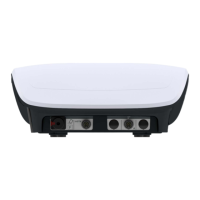
Figure 5.2 Unit rear panel view ................................................................................................................................................ 16
Figure 5.3 Arrangement of front panel components ............................................................................................................... 17
Figure 5.4 The battery installation method .............................................................................................................................. 19
Figure 5.5. Rough diagram of the output circuit of the unit working in CV mode (one channel) ............................................. 20
Figure 5.6. Presentation of information about the high resistance in the patient circuit ........................................................ 21
Figure 5.7. Signalization of worn electrodes ............................................................................................................................ 22
Figure 6.1 Electrotherapy sockets label.................................................................................................................................... 24
Figure 6.2. Connection of electrodes ....................................................................................................................................... 24
Figure 6.3. Supply part label ..................................................................................................................................................... 25
Figure 7.1 Field description ...................................................................................................................................................... 31
Figure 7.2 Screenshot sample view for dual circuit electrotherapy A+B .................................................................................. 34
Figure 7.3 Screenshot sample view for single circuit electrotherapy A and B .......................................................................... 35
Figure 7.4 Screenshot sample view for electrotherapy sequences .......................................................................................... 35
Figure 7.5 Information screen sample view ............................................................................................................................. 36
Figure 8.1. Manual time setting ............................................................................................................................................... 45
Figure 10.1. The unit error signaling and information visible after closing of the error message ............................................ 84
List of tables
Table 4.1. Recommendations for the operation of touch screens ........................................................................................... 13
Table 4.2. Essential performance and basic safety testing recommendations ......................................................................... 14
Table 5.1 Description of front panel components .................................................................................................................... 17
Table 5.2. Non-battery unit ...................................................................................................................................................... 18
Table 5.3. Unit equipped with battery ..................................................................................................................................... 18
Table 5.4. Additional information about battery indicator ...................................................................................................... 18
Table 5.5. The battery installation method .............................................................................................................................. 19
Table 5.6. Currents classification .............................................................................................................................................. 23
Table 8.1. Permitted amplitude values in relation to pulse duration ....................................................................................... 61
Table 8.2. Available frequency values in relation to pulse duration ........................................................................................ 70
Table 10.1. Signaling special messages .................................................................................................................................... 84
Table 10.2. The "hardware" error coding system ..................................................................................................................... 85
Table 10.3. ................................................................................................................................................................................ 85