176
2467S–AVR–07/09
ATmega128
Frame Formats A serial frame is defined to be one character of data bits with synchronization bits (start and stop
bits), and optionally a parity bit for error checking. The USART accepts all 30 combinations of
the following as valid frame formats:
• 1 start bit
• 5, 6, 7, 8, or 9 data bits
• no, even or odd parity bit
• 1 or 2 stop bits
A frame starts with the start bit followed by the least significant data bit. Then the next data bits,
up to a total of nine, are succeeding, ending with the most significant bit. If enabled, the parity bit
is inserted after the data bits, before the stop bits. When a complete frame is transmitted, it can
be directly followed by a new frame, or the communication line can be set to an idle (high) state.
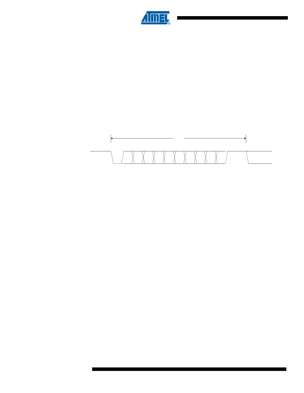
Figure 82 illustrates the possible combinations of the frame formats. Bits inside brackets are
optional.
Figure 82. Frame Formats
St Start bit, always low.
(n) Data bits (0 to 8).
P Parity bit. Can be odd or even.
Sp Stop bit, always high.
IDLE No transfers on the communication line (RxD or TxD). An IDLE line must be
high.
The frame format used by the USART is set by the UCSZ2:0, UPM1:0 and USBS bits in UCSRB
and UCSRC. The receiver and transmitter use the same setting. Note that changing the setting
of any of these bits will corrupt all ongoing communication for both the receiver and transmitter.
The USART Character SiZe (UCSZ2:0) bits select the number of data bits in the frame. The
USART Parity mode (UPM1:0) bits enable and set the type of parity bit. The selection between
one or two stop bits is done by the USART Stop Bit Select (USBS) bit. The receiver ignores the
second stop bit. An FE (Frame Error) will therefore only be detected in the cases where the first
stop bit is zero.
Parity Bit Calculation The parity bit is calculated by doing an exclusive-or of all the data bits. If odd parity is used, the
result of the exclusive or is inverted. The relation between the parity bit and data bits is as
follows:
P
even
Parity bit using even parity
P
odd
Parity bit using odd parity
d
n
Data bit n of the character
If used, the parity bit is located between the last data bit and first stop bit of a serial frame.
10 2 3 4 [5] [6] [7] [8] [P]St Sp1 [Sp2] (St / IDLE)(IDLE)
FRAME
P
even
d
n 1–
… d
3
d
2
d
1
d
0
0
P
odd
⊕⊕⊕⊕⊕⊕
d
n 1–
… d
3
d
2
d
1
d
0
1⊕⊕⊕⊕⊕⊕
=
=