61
2467S–AVR–07/09
ATmega128
Notes: 1. When the BOOTRST fuse is programmed, the device will jump to the Boot Loader address at
reset, see “Boot Loader Support – Read-While-Write Self-Programming” on page 273.
2. When the IVSEL bit in MCUCR is set, interrupt vectors will be moved to the start of the Boot
Flash section. The address of each interrupt vector will then be address in this table added to
the start address of the boot Flash section.
3. The Interrupts on address $0030 - $0044 do not exist in ATmega103 compatibility mode.
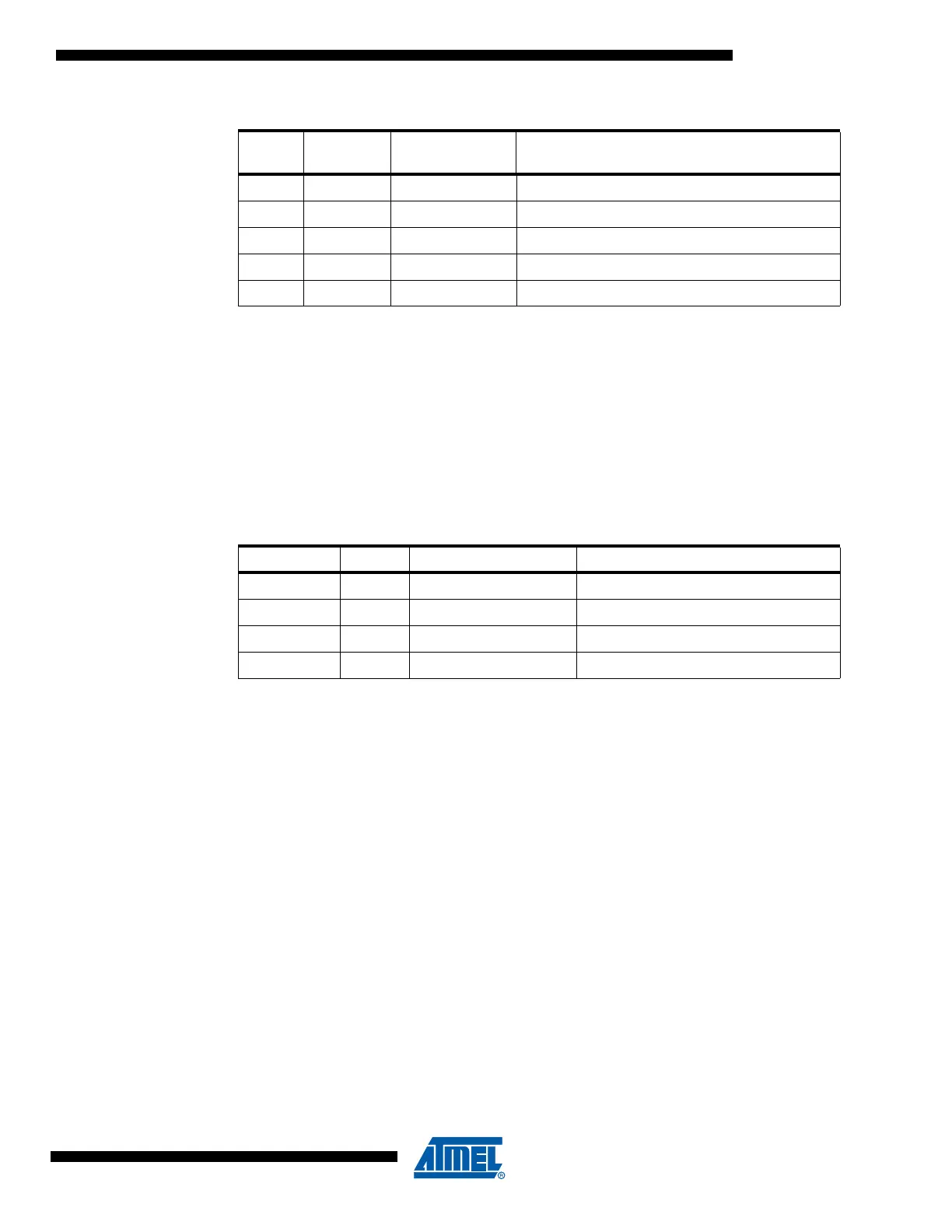
Table 24 shows Reset and interrupt vectors placement for the various combinations of
BOOTRST and IVSEL settings. If the program never enables an interrupt source, the interrupt
vectors are not used, and regular program code can be placed at these locations. This is also
the case if the Reset Vector is in the Application section while the interrupt vectors are in the
Boot section or vice versa.
Note: The Boot Reset Address is shown in Table 112 on page 284. For the BOOTRST fuse “1” means
unprogrammed while “0” means programmed.
31 $003C
(3)
USART1, RX USART1, Rx Complete
32 $003E
(3)
USART1, UDRE USART1 Data Register Empty
33 $0040
(3)
USART1, TX USART1, Tx Complete
34 $0042
(3)
TWI Two-wire Serial Interface
35 $0044
(3)
SPM READY Store Program Memory Ready
Table 24. Reset and Interrupt Vectors Placement
BOOTRST IVSEL Reset Address Interrupt Vectors Start Address
1 0 $0000 $0002
1 1 $0000 Boot Reset Address + $0002
0 0 Boot Reset Address $0002
0 1 Boot Reset Address Boot Reset Address + $0002
Table 23. Reset and Interrupt Vectors (Continued)
Vector
No.
Program
Address
(2)
Source Interrupt Definition