160
7647H–AVR–03/12
Atmel ATmega16/32/64/M1/C1
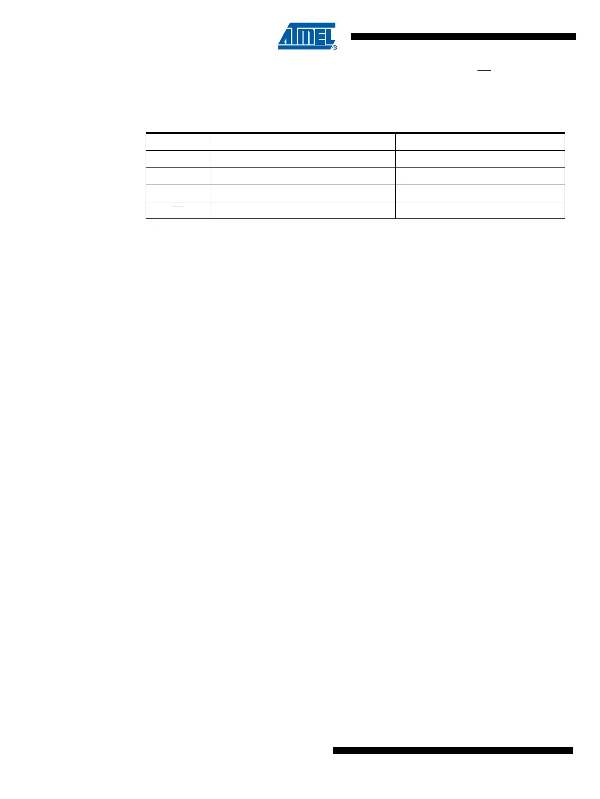
When the SPI is enabled, the data direction of the MOSI, MISO, SCK, and SS pins is overridden
according to Table 15-1. For more details on automatic port overrides, refer to “Alternate Port
Functions” on page 67.
Note: 1. See “Alternate Functions of Port B” on page 69 for a detailed description of how to define the
direction of the user defined SPI pins.
The following code examples show how to initialize the SPI as a Master and how to perform a
simple transmission.
DDR_SPI in the examples must be replaced by the actual Data Direction Register controlling the
SPI pins. DD_MOSI, DD_MISO and DD_SCK must be replaced by the actual data direction bits
for these pins. E.g. if MOSI is placed on pin PB2, replace DD_MOSI with DDB2 and DDR_SPI
with DDRB.
Table 15-1. SPI Pin Overrides
(1)
Pin Direction, Master SPI Direction, Slave SPI
MOSI User Defined Input
MISO Input User Defined
SCK User Defined Input
SS User Defined Input
 Loading...


