106 User’s Manual—SNAP™ 700 Printer
Classification: Avery Dennison - Public
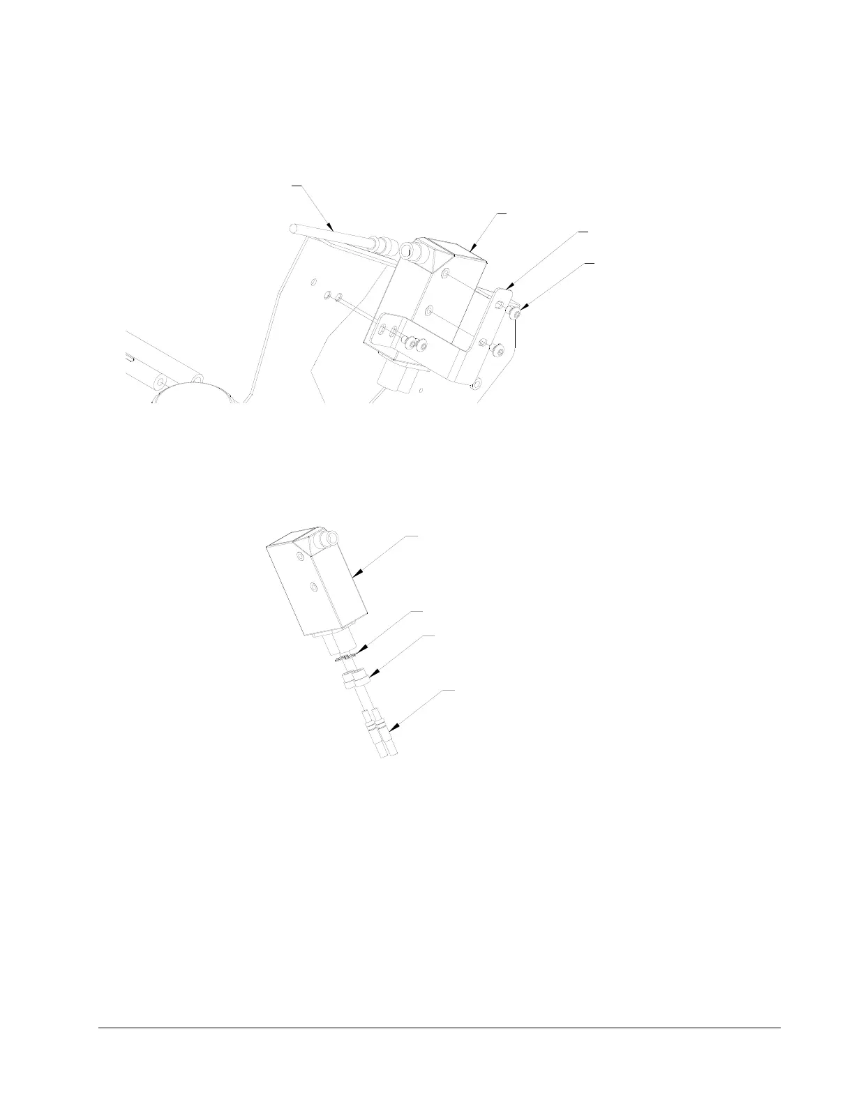
8. Assemble Sensor Mounting Bracket to Sensor body with two 6-32 x ¼ Button Head
Screws.
MCB POWER CABLE CONNECTOR
SENSOR MOUNTING BRACKET
(4) 10-32 X 1/4 BUTTON HEAD SCREWS
SENSOR
9. Remove two plastic Jam Nuts from Sensor, slide ends of “Y” Cable through nuts and
secure with two 7/32 E-Rings.
10. Insert the threaded Plastic Nuts in the Sensor receptacles, firmly seating the fiber-Optic
Cable ends and tighten the Plastic Nuts.
7/32 E-RING
FIBER OPTIC CABLE END ("Y" END)
PLASTIC NUT
SENSOR
11. Assemble the Sensor / Bracket / Lead Assembly to the Upright Frame using (2) Pem
Nuts shown above. Use 10-32 x ¼ Button Head Screws supplied with kit.
12. Assemble Sensor Power Cable to Sensor and plug into MCB Connector labeled
“Option Top Color / Contrast”.