User’s Manual—SNAP™ 700 Printer 103
Classification: Avery Dennison - Public
11.4 Factory / Field Installation of Top Sensor
Assemblies
These Sensors are alike in mechanical configuration. 05620006 is a Contrast Sensor
Assembly only and 05620007 is a Color Contrast Assembly
11.4.1 Installation Procedure
1. Disconnect Power to Printer
2. Disconnect Stacker Interface Cable
3. Remove the Rear Cover (save screws)
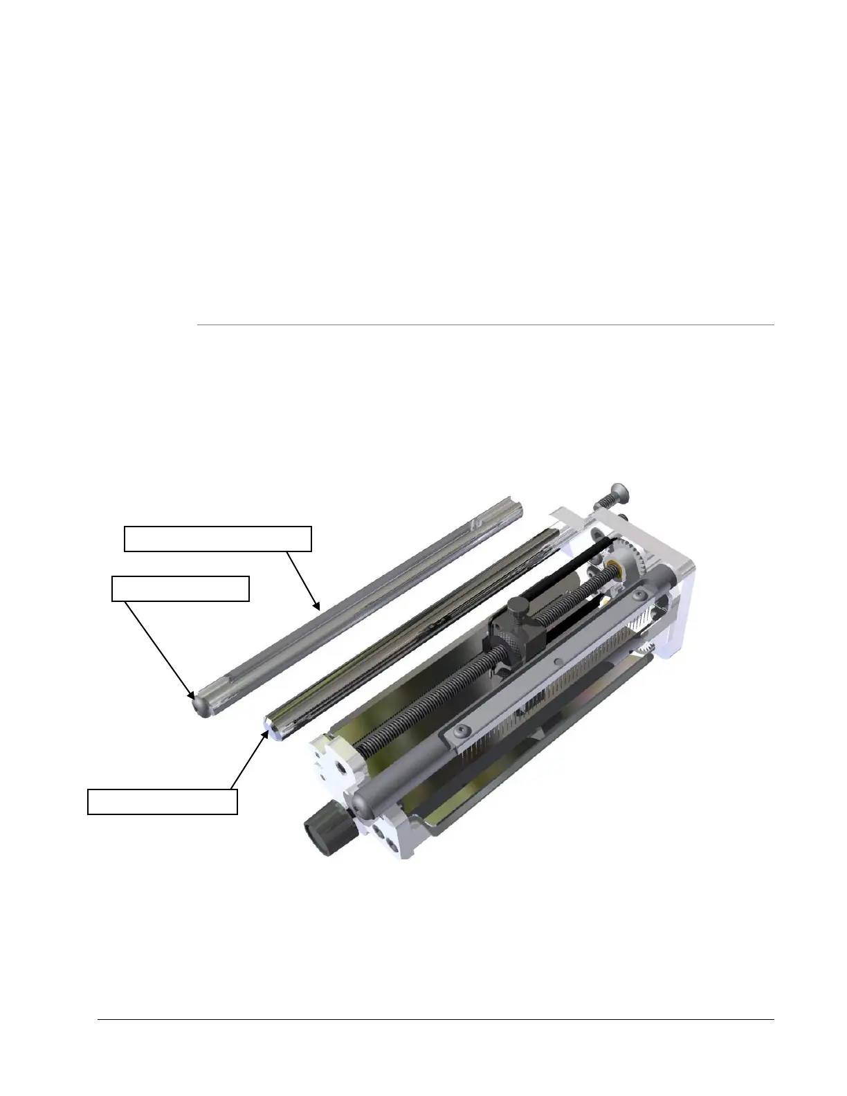
4. Remove the existing Sensor Tray Assembly and remove the Web Turn Shaft located on
the left side. Replace with the Slotted Web Turn Shaft so that the larger slot is in the
upper position as shown. Install the ¼-20 x 3/8 Button Head Cap Screw on the end of
the shaft.