Specification T1689 Technical Manual Rev 07
DELTA Rectifier Module MV3000 Air Cooled DELTA
Page 44
2.9.2.9 Pre-Charge
Pre-charge requirements are listed in Table 2–22. The pre-charge control signal switches in the main rectifiers
when the d.c. link has finished pre-charging. The drive controller determines when the charging period is
complete.
The rectifier pre-charge acknowledge signal must be connected to the MV3000e controller at PL12, to allow
drive operation. See Table 2–11.
An external 110 Va.c. auxiliary supply is required to energise the internal pre-charge contactor on the 500 - 690
V GDR rectifiers.
Pre-charge
Voltage
Load
Required
Table 2–22. – Pre-Charge Requirements
NOTE: * Requires an Inrush/Hold of 65/9 VA.
2.9.2.10 Thermal Protection
Thermal protection is provided on each rectifier module by a thermistor on the upper heatplate and a
thermostat located on the lower heatplate (if fitted). Connection details are given in Table 2–11. The
thermostat contact is a normally closed contact and opens at 90°C ±3°C (194°F ±5°F).
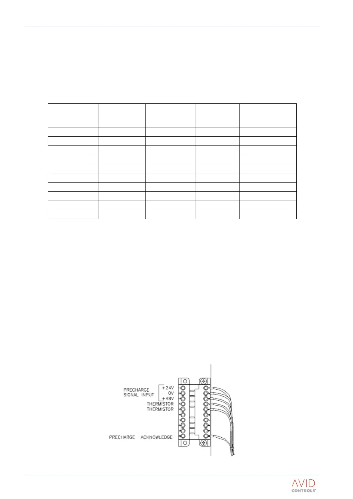
2.9.2.11 Electrical Connections
Control Connections
The rectifier control terminals are mounted at the top of the front face of the rectifier module.
See Figure 2–9.
The customer terminals are the left half of a 10-pin plug and socket, referenced TB1, and may be unplugged for
ease of wiring. See Figure 2–10 to Figure 2–13 for the terminal layouts and functions.
Figure 2–10. – Rectifier Bridge Module Terminals (GDR391-4401 & GDR721-4401))