T1689 Technical Manual Rev 07 Specification
MV3000 Air Cooled DELTA DELTA Rectifier Module
Page 51
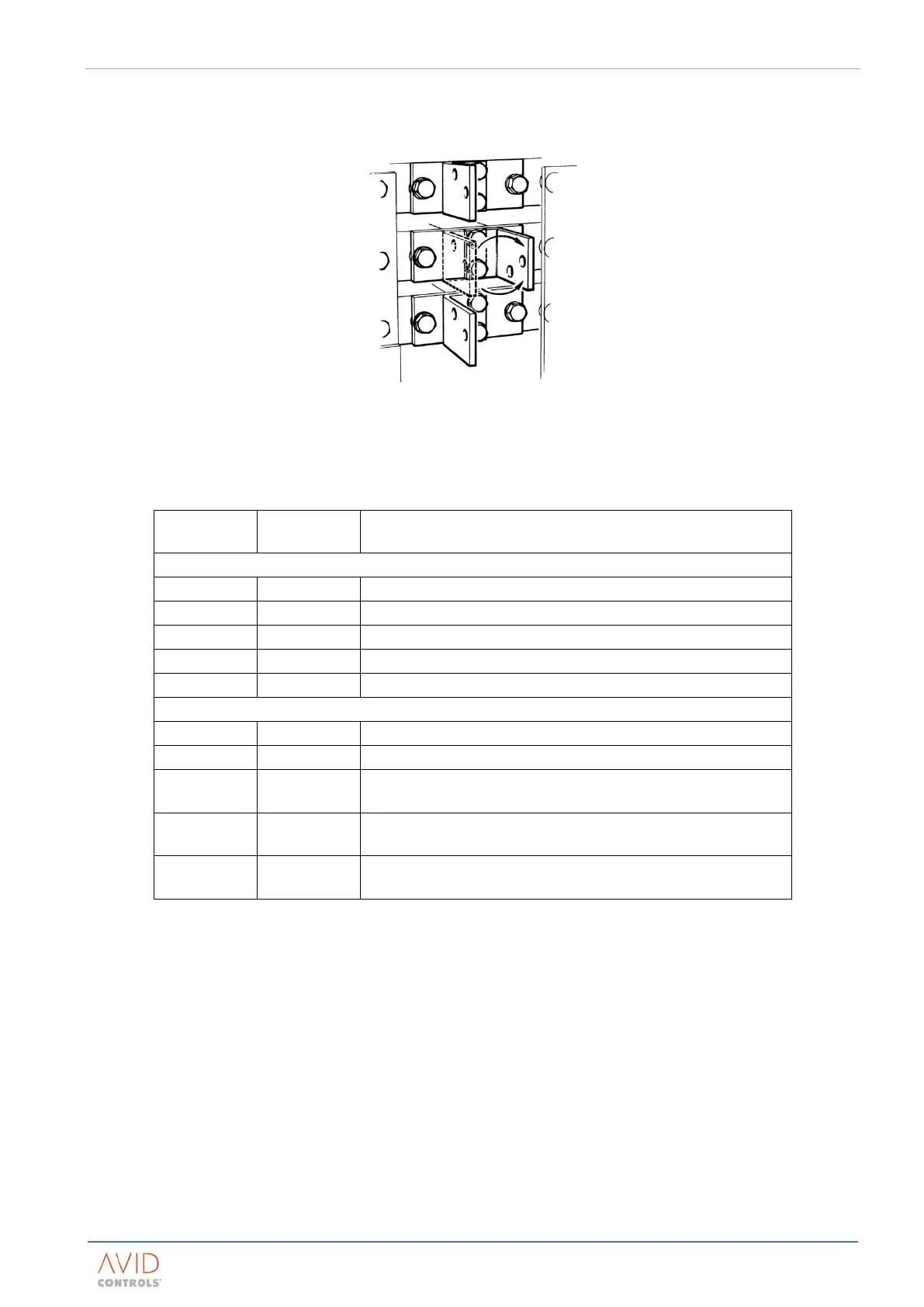
Cabling of phase power terminals for GDR721, 872 & 1168
When cabling to the phase terminals of these rectifiers the centre terminal may be rotated through 180° to
increase the clearance distance between the cable crimp and the adjacent terminal.
Figure 2–19. – Rotation of Centre Phase Terminal for Cable Connection
Terminations
Description of termination
M10 stud for cable ring crimp (use M10 or 3/8 in crimp)
M10 stud for cable ring crimp (use M10 or 3/8 in crimp)
50 x 6.3 (2 x ¼ in) busbar with 2 x 10.5 mm holes
63 x 6.3 (2½ x ¼ in) busbar with 2 x 10.5 mm holes
50 x 6.3 (2 x ¼ in) busbar with 2 x 10.5 mm holes
M10 insert for cable ring crimp (use M10 or 3/8 in crimp)
M10 insert for cable ring crimp (use M10 or 3/8 in crimp)
63 x 6.3 (2½ x ¼ in) busbar with 2 x M10 threaded inserts / studs
for cable ring crimps (use M10 or 3/8 in crimp)
80 x 6.3 (3 x ¼ in) busbar with 4 x M10 threaded inserts for cable
ring crimps (use M10 or 3/8 in crimp)
63 x 6.3 (2½ x ¼ in) busbar with 2 x M10 threaded inserts / studs
for cable ring crimps (use M10 or 3/8 in crimp)
Table 2–23. – Terminations for 3-Phase Supply & DC Output
The a.c. terminals are suitable for a maximum of 2 x 150 mm
2
cables (2 x 300 MCM in North America).
To achieve the full current rating of the product, it may be necessary to use high temperature cable.
See Section 3 – Drive (CDM) Design
NOTE: Do not allow the temperature of the cable to exceed 125°C (257°F).
The d.c. positive terminals are suitable for a maximum size of busbar at 76 mm x 6.3 mm wide (= 3 in x ¼ in).
The d.c. negative terminals are suitable for a maximum size of busbar at 140 mm x 6.3 mm wide (≈ 5½ in x
¼ in). Ratings and sizes of busbars are application dependent.
 Loading...