Installation location:
Author: Date:
C 4
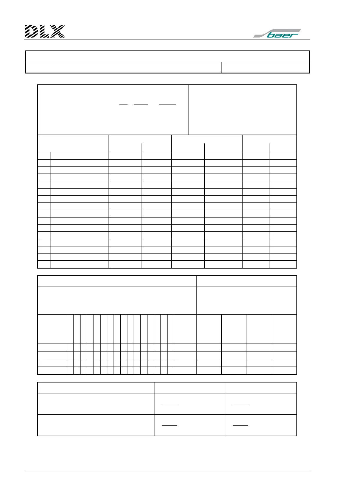
Pulse rates (quantization):
KR
W
Y
X
w
w
×
=
(
K
Const
)
X
w
, Y
w
: Numerator and divisor (no decimal), 8
digits
W: Transformer ratio (U
prim
/U
sec
× I
prim
/I
sec
)
R: Meter constant [pulses/kWh]
Const: Impulse constant [kWh/pulse]
K: Reading constant
w: Energy („work“)
P
min
: Minimum of demand value
P
: Maximum of demand value
Pulse inputs Reading constant Meter & transformer ratio
Energy
P
/ P
K R
[puls./kWh]
W X
Y
1
2
3
4
5
6
7
8
9
10
11
12
13
14
15
16
Sums intergration
Maximum pulse frequecy for output:
f
max
[Hz]
= P
max
[kW]
/ IA
s
[kWh/pulse]
× 1 / 3600
IA: Output [kWh/pulse]
K: Reading constant
s: Sum
P
max
: maximum of demand value
f
: maximum puls frequency for output
Sum
Output
IA
s
[kWh/pul.]
Maximum
value
P
max
[kW]
Readin
constante
K
s
Hysteresis
Hs
[kWh]
Max.
frequency
f
max
[Hz]
Σ1:
Σ2:
Σ3:
Σ4:
Apparent demand and cosine phi 1 2
Active demand:
Input
Sum+
Sum-
Input
Sum+
Sum-
Reactive demand:
Input
Sum+
Sum-
Input
Sum+
Sum-