47
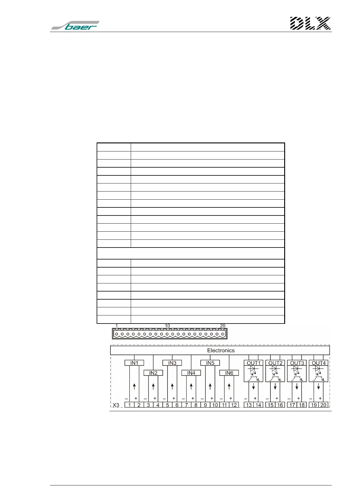
5.4.4 Connector X3 (Pulse inputs 1-6, outputs 1-4)
Terminal type: Combicon MSTB2,5/10-ST-5,08 (Phoenix),
2 per input / output card
Function: Inputs (In1 to In6, terminal 1 to 12)
Electronic outputs (Out1 to Out4, terminal 13 to
20)
Types of inputs / outputs: 6 input modules (IES, IEW, IED, signal current)
4 output modules (solid state IAW el., max.
250V/100mA)
Terminal Description
1 Pulse input In1– IN1
2 Pulse input In1+
3 Pulse input In2– IN2
4 Pulse input In2+
5 Pulse input In3– IN3
6 Pulse input In3+
7 Pulse input In4– IN4
8 Pulse input In4+
9 Pulse input In5– IN5
10 Pulse input In5+
11 Pulse input In6– IN6
12 Pulse input In6+
Freely programmable outputs
13 Electronic output Out1– OUT1
14 Electronic output Out1+
15 Electronic output Out2– OUT2
16 Electronic output Out2+
17 Electronic output Out3– OUT3
18 Electronic output Out3+
19 Electronic output Out4– OUT4
20 Electronic output Out4+
Figure 20, Connector X3
When IED (bi-current / bi-polar) Modules are used, then the signal
conditioning must be adjusted by means of the programming soft-
ware "DLXPARA".
When using mixed types of pulse inputs, the IES type modules are lo-
cated at the left hand side.