81
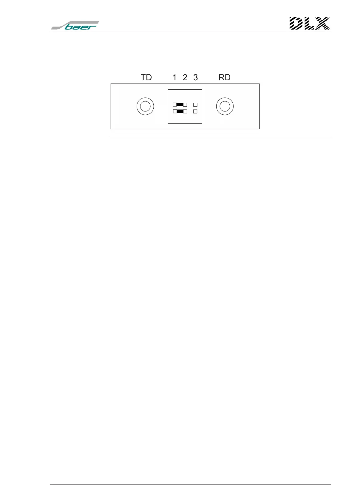
8.3.5 Pin allocation of the fiber-optic connector
Using the fiber-optic connector (for fiber-optic transmission), the unit can be
read via 820nm optical fiber (glass).
Figure 43, Fiber-optic connector
•
Wave length: 820nm
•
Transmitter (TD): transmits light
•
Receiver (RD): receives light
•
Cable code: 50/125
µ
m, 62,5/125
µ
m (recommendation),
100/140
µ
m or 200
µ
m HCS (Multimode)
•
Connection code: ST or SMA
•
Baud rate: 300 to 9600 Baud
•
Cable length: max. 2,7km (depends of the cable)
•
Communication protocol: SCTM or IEC60870-5-102
(alternatively Modbus RTU)
The idle condition of the fiber-optic transmission line has to be configured
with the jumpers between the two connector elements:
•
Idle condition „Light off“:
the jumper must be placed on pins 1/2 (deliv-
ery condition)
•
Idle condition „Light on“:
the jumper must be placed on pins 2/3
The upper row of pins determines the condition of the receiver (RD), the
lower row of pins sets the condition for the transmitter (TD). Jumpers must
be placed in both rows!