83
8.3.7 Pin allocation of the RS485 (2 wires)
With a RS485 interface module the unit can be used in a bus system, as
described in the standard ANSI/TIA/EIA-485-A-98.
•
Voltage: 0VDC / 5VDC
•
Number of partner: max. 32
•
Cable length: max 1.2km
•
Baud rate: 300 to 9600 Baud (fix baud rate)
•
Communication protocol: SCTM or IEC 60870-5-102
(alternatively Modbus RTU)
•
Termination (120
Ω
): none
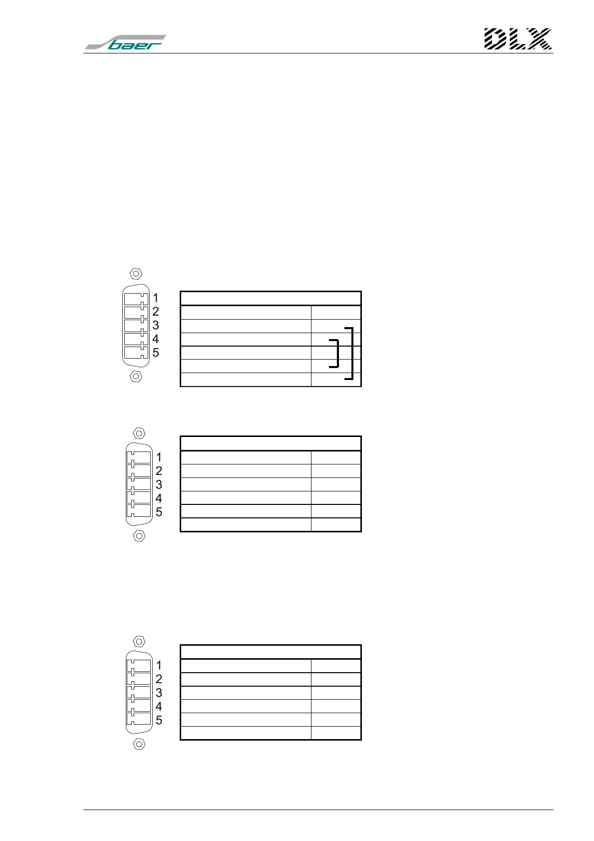
Pin allocation at housing for panel mounting (Com2/X5 or Com1/X6)
and at 19”-rack (only Com2/X7):
DLX (5 pins, male)
Function Pin No.
B (–)
A (+)
GND
A (+) Bridge to 2
B (–) Bridge to 1
Baud rate: 300 to 9600 Baud
Pin allocation at 19”-rack (only Com1/X6):
DLX (5 pins, male)
Function Pin No.
—
A (+)
B (–)
—
GND
Baud rate: 300 to 9600 Baud
8.3.8 Pin allocation of the RS485 (4 wires)
With a RS485 interface module the unit can be used in a bus system, as
described in the standard ANSI/TIA/EIA-485-A-98.
Pin allocation at 19”-rack (only Com1/X6):
DLX (5 pins, male)
Function Pin No.
D (A–)
T (B+)
T (A–)
D (B+)
GND
Baud rate: 300 to 9600 Baud
Note: Possible at 19”-rack only!