80
8.3.4 Pin allocation of the M-Bus data interface
With a passive M-Bus interface module the unit can be used in a M-Bus
system, as described in the standard TC 176/N17 Part 3:
•
Typical M-Bus voltage: 24V to 42V
•
Max. M-Bus voltage: 50V
•
Idle current: < 2mA
•
Working current: 10 to 20mA
•
Baud rate: 300 to 2400 Baud (with good lines up to 9600)
Note: up to 9600 Baud at 19”-rack (connector
X6)
•
M-Bus length: max. 5km
•
Communication protocol: SCTM or IEC60870-5-102
(alternatively Modbus RTU)
•
Connection: via terminals
The distance between the DLX and the next M-Bus repeater unit can ex-
ceed 5 km. The maximum distance depends on the line conditions and the
current burden on the M-Bus. With sufficient line diameter, twisted lines and
limitations on the baud rate, up to double the value of the above mentioned
distance can be achieved.
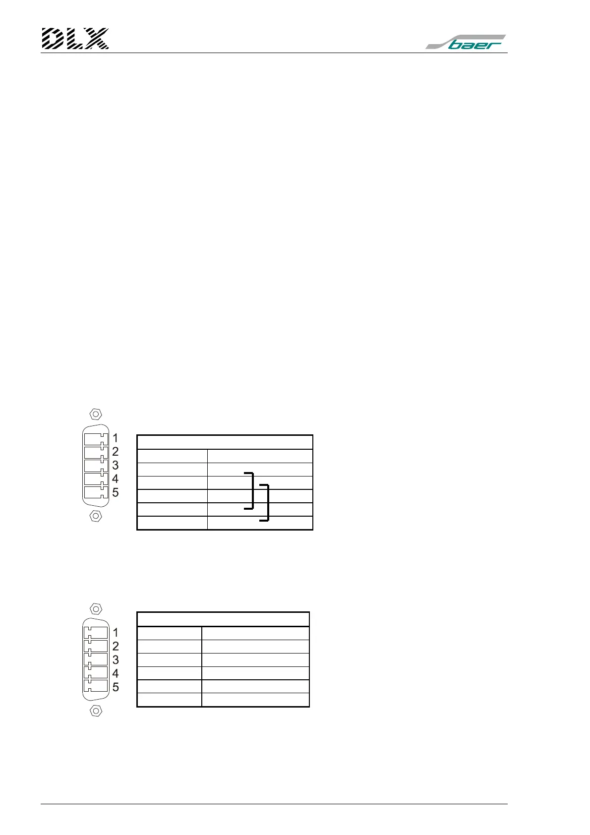
Pin allocation at housing for panel mounting (Com2/X5 or Com1/X6)
and at 19”-rack (only Com2/X7):
DLX (5 pins, male)
Function Pin No.
M-Bus
M-Bus
—
Bridge to 1
Bridge to 2
Baud rate: 300 to 2400 Baud (with good lines up to 9600 Baud)
The two M-Bus terminals 1 and 2 present twice and bridged internally
(with 4 and 5)
Pin allocation at 19”-rack (only Com1/X6):
DLX (5 pins, male)
Function Pin No.
—
M-Bus
M-Bus
—
—
Baud rate: 300 to 9600 Baud