78
8.2 Service interface
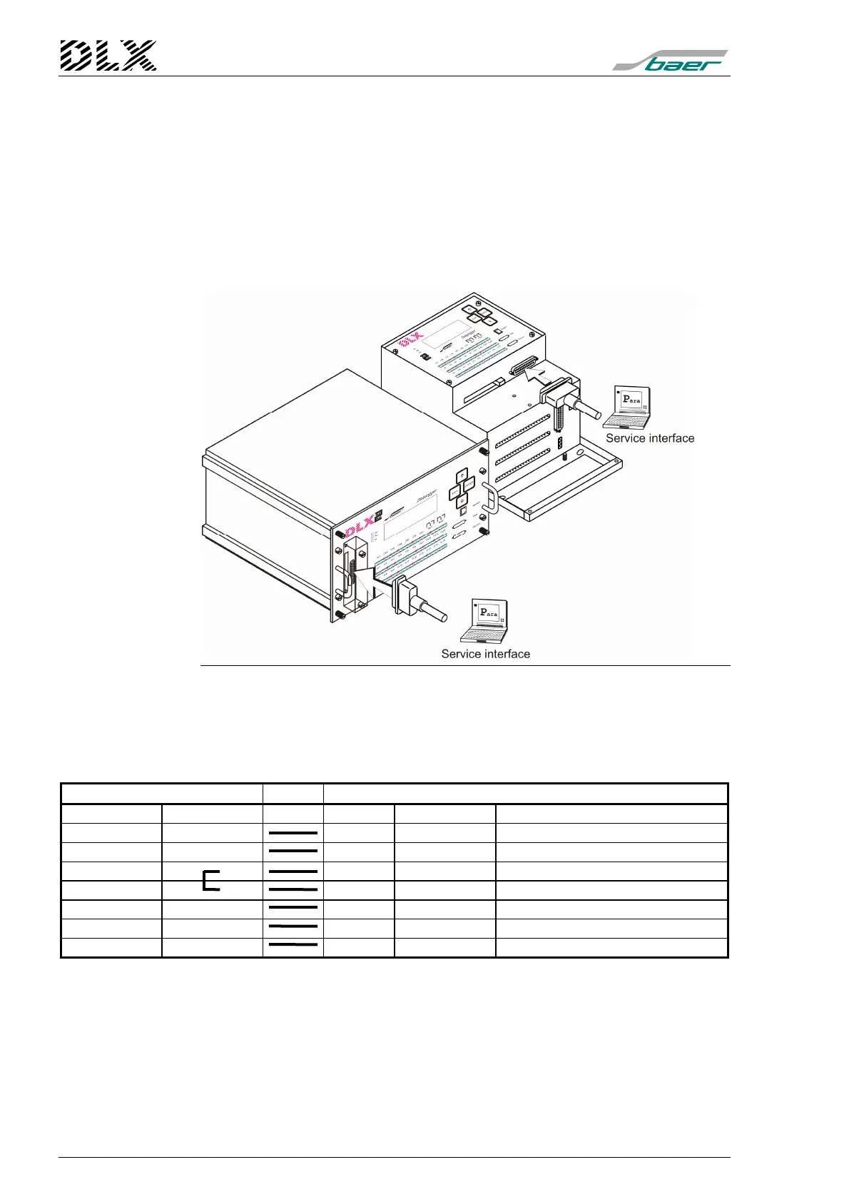
The service interface is used to program the DLX unit and to retrieve data
with a fixed baud rate (9600 baud). It is implemented as a 25 pin SUB-D
connector (female) according to ISO2110, the pin allocation is according to
V.24/RS232C/DIN 66020.
Programming of the DLX is done using the programming software
DLXPARA. Please read the user manual of the programming software
DLXPARA for instructions on programming.
Figure 42, Service interface
8.2.1 Pin allocation of the SUB-D (female) service interface RS232
Standard: RS232
Type: SUB-D female
DLX (25 pins, female) cable PC (25 pins, male)
Input/Output Pin No. Pin No. Input/Output Standard usage
Input
Output TxD (transmit data)
Output
Input RxD (receive data)
Input
Output RTS (request to send)
Output
Input CTS (clear to send)
Output
Input DSR (data set ready)
GND (protective earth)
Input
Output DTR (data terminal ready)
8.2.2 Connection PC/Laptop ↔
↔↔
↔ Service interface
For the connection between a DLX and a PC, a programming cable or mo-
dem cable (#6998) is required. Plug the programming cable into a free
COM port of the PC/Laptop and into the service interface of the DLX. Now
you can start the required software (programming or data retrieval).