79
8.3 Data interface Com1 and Com2
The optional data interface can be used for data retrieval on site with data
retrieval software (e.g. SIGLON) or to connect to an external modem. The
baud rate can be set with DLXPARA to a value between 300 and 9600
baud. It is implemented as a 25 pin SUB-D connector (female) according to
ISO2110, the pin allocation is according to V.24/RS232C/DIN 66020.
Alternatively a 25 pin SUB-D male connector, a bus interface (20mA/CS,
M-Bus or RS485) or a FO connector (fiber-optic transmission connection)
can be used.
8.3.1 Pin allocation RS232 SUB-D (female)
The standard pin allocation of the data interface is identical with the service
interface (see page 78). For the connection between the DLX and a PC, a
modem cable is required. For the connection between a DLX and an exter-
nal modem a so-called null modem cable (crossed wires) is required.
8.3.2 Pin allocation RS232 SUB-D (male)
For the connection between the DLX and a PC, a null modem cable
(crossed wires) is required. For the connection between a DLX and an ex-
ternal modem a modem cable is required (1 to 1).
DLX (25 pins, male) cable PC (25 pins, male)
Input/Output Pin No. Pin No. Input/Output Standard usage
Output
Output TxD (transmit data)
Input
Input RxD (receive data)
Output
Output RTS (request to send)
Input
Input CTS (clear to send)
GND (protective earth)
Input
Input DSR (data set ready)
Output
Output DTR (data terminal ready)
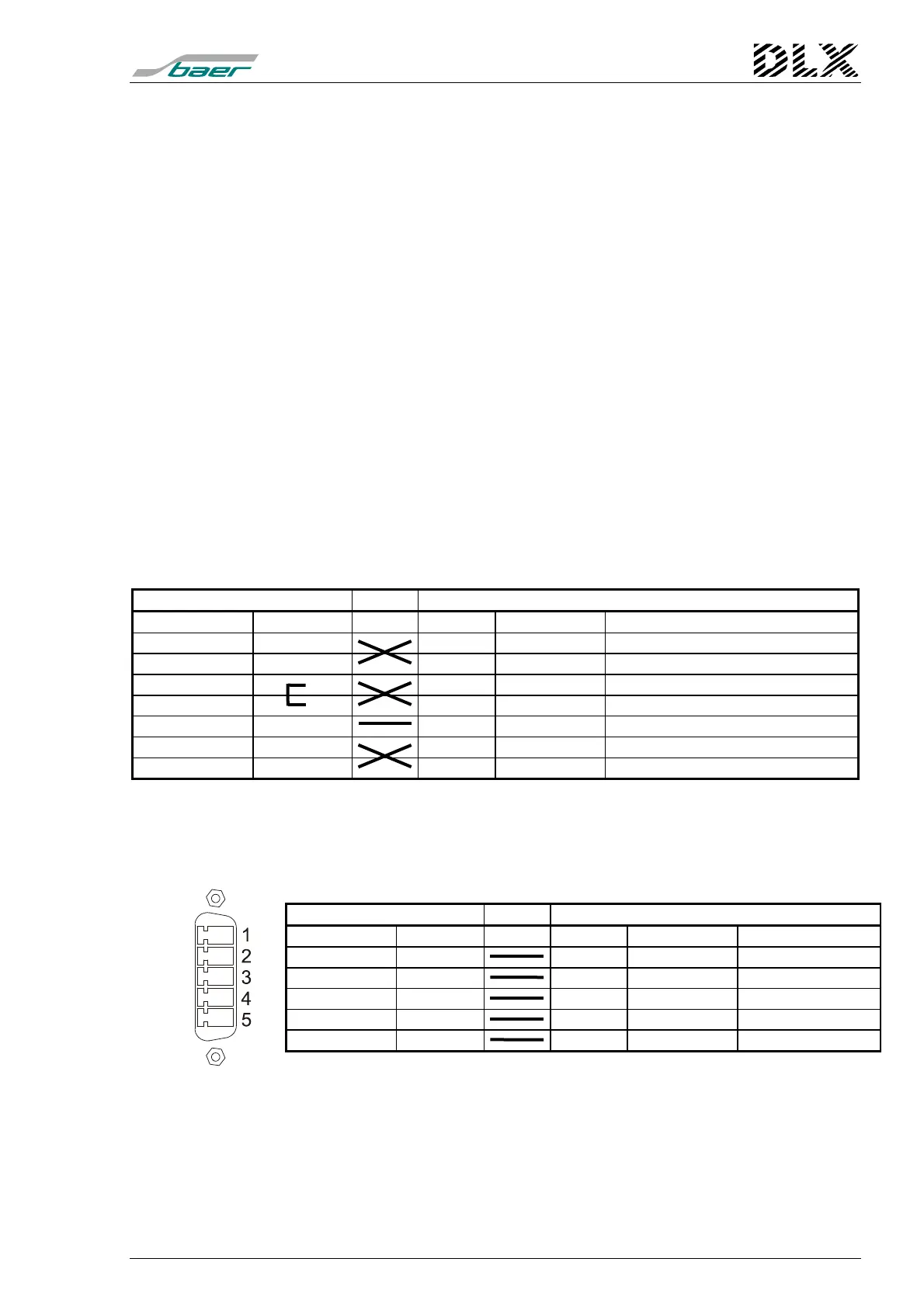
8.3.3 Pin allocation RS232 (Com1/X6 at 19”-rack only)
For the connection between the DLX and a PC, a special cable (5 wires) is
required.
Identification: Phoenix 5 pins PSC 1,5/5-M.
DLX (5 pins, male) cable PC (25 pins, male)
Input/Output Pin No. Pin No. Input/Output Standard usage
Input
Output RTS
Input
Output TxD
Output
Input RxD
Output
Input CTS
GND
Baud rate: 300 to 9600 Baud