4. Troubleshooting
Code 6061: “+24v - voltage high” (Warning)
Situation Solution
Malfunction Fan Control board or
SMPS board.
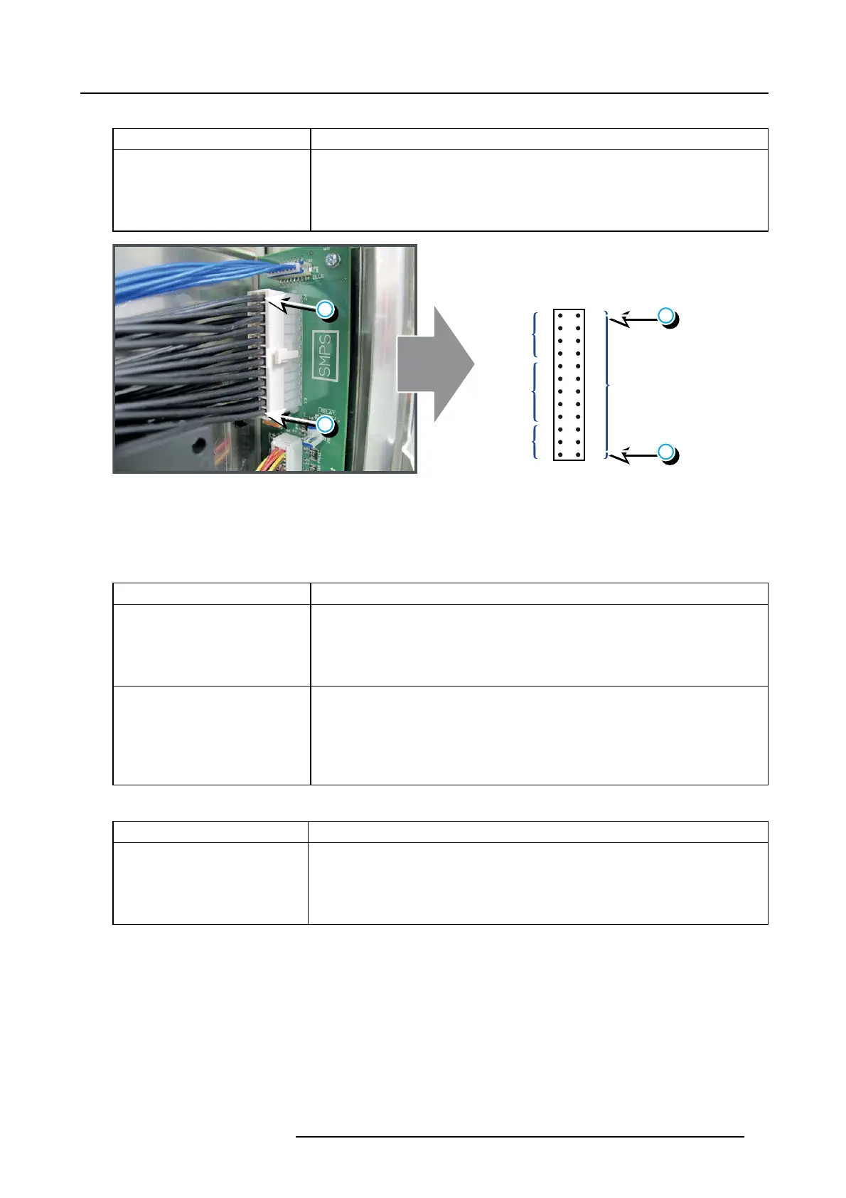
Measure on the Signal Backplane the +24V voltage on pin 9, 10, 11 or 12 of the
connector of the black wire unit which com es from the SMP S board. Se e im age 4-43.
If the measured voltage is about 24V then replace the Fan Control board. See
"Removing a board in the card cage", page 213. O therwise replace the SMP S board.
See"Replacement of the S witched M ode Power Sup ply", page 281.
12 24
+24V
11 23
10 22
921
820
+VTEC
GND
719
618
517
416
315
++12V
214
113
24
24
13
13
Image 4-43
Code 6062: “+24v - voltage too low” (Error)
This error code is probably preceded by the w arning code 6063: “+24v - v oltage low”. The same troubleshooting table can be
applied.
Code 6063: “+24v - voltage low” (Warning)
Situation Solution
Malfunction Fan Control board or
SMPS board.
Measure on the Signal Backplane the +24V voltage on pin 9, 10, 11 or 12 of the
connector of the black wire unit which com es from the SMP S board. Se e im age 4-43.
If the measured voltage is about 24V then replace the Fan Control board. See
"Removing a board in the card cage", page 213. O therwise replace the SMP S board.
See"Replacement of the S witched M ode Power Sup ply", page 281.
Short circuit or b ad connection.
1. Check the Signal Backplane for bad con nections. Ensure that all wire units ar e
well connected.
(Note that the +24V supply is generated on the SMPS board and enters the F an
Control board and Cinema Control board via the Signal Back plane)
2. Check the wirin g of the A node fan for short circuits.
3. Check the w iring of the Cathode fan for s hort circuits.
Code 6071: “++12v - voltage high” (Warning)
Situation Solution
Malfunction Fan Control board or
SMPS board.
Measure on the Signal Backplane the ++12V voltage on pin 1, 2 or 3 of the connector of
the black wire unit which comes from the SM PS boar d. See image 4-43.
If the measured voltage is about12V then replace the F an C ontrol board. See
"Removing a board in the card cage", page 213. Otherwise replace the SMPS board.
See"Replacement of the Switched Mode Power Supply", page 281.
R5905043 DP2K-12C/11CX 19/02/2018 71