R5906790 /04 Athena50
7.4 Cinema Controller
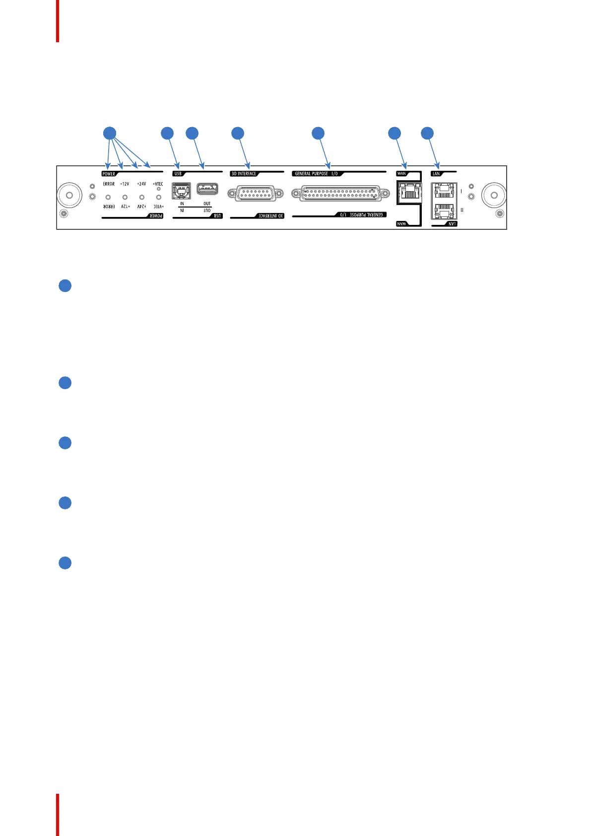
Location of the communication ports
Image 7-4
Functionality
Diagnostic LEDs
The front plate of the Cinema Controller contains 4 diagnostic LEDs to display the status of the power
supply (reference 6 Image 7-4):
• +VTEC supply (not used on Athena).
• +24V supply.
• +12V supply.
• general power supply (ERROR).
USB IN port
The Cinema Controller is equipped with a USB port, type “B” connector, (reference 5 Image 7-4) to
connect upstream devices (E.g. PC). This USB port is used to communicate with the projector via RS232
commands (Virtual comport). The USB IN port remains operational in Sleep mode.
USB OUT port
The Cinema Controller is equipped with a USB port, type “A” connector, (reference 4 Image 7-4) which
can be used to power handheld devices within USB spec (MAX 500mA/5V]. No other functionality
supported (Future expansion). The USB OUT port remains operational in Sleep mode.
3D INTERFACE
3D interface port (reference 3 Image 7-4). Can be used to connect external 3D devices to the projector.
All signals necessary for 3D projection can be provided via this connector. The 3D interface port is
disabled if the projector is in Sleep mode.
GENERAL PURPOSE INPUT/OUTPUT (GPIO)
This 37 pin connector (reference 2 Image 7-4) can be used to send or receive trigger signals from other
devices. These input/output pins can be programmed by macros created with the Communicator
software. See user's guide of the Communicator, section Macro editor, for more information about this
functionality. Note that the General Purpose Inputs accept 24 volt maximum. The GPIO remains
operational when the projector is in Sleep mode. So, if the factory predefined macro to wake up the
projector is assigned to one of the free GPI input pins the projector can be awakened via GPIO.
Enter or leave Sleep mode can also be done with GPIO via two predefined Macros (not editable).
Input & Communication