EasyManuals Logo

Basler BE1-11g User Manual

Basler BE1-11g
672 pages
To Next Page IconTo Next Page
To Previous Page IconTo Previous Page
Page #101 background imageLoading...
Page #101 background image
9424200994 Rev N 89
Table 29. Logic Inputs and Outputs
Name
Logic Function
Purpose
Block
Input
Disables the 50 function when true
Trip
Output
True when the 50 element is in a trip condition
Pickup
Output
True when the 50 element is in a pickup condition
Operational Settings
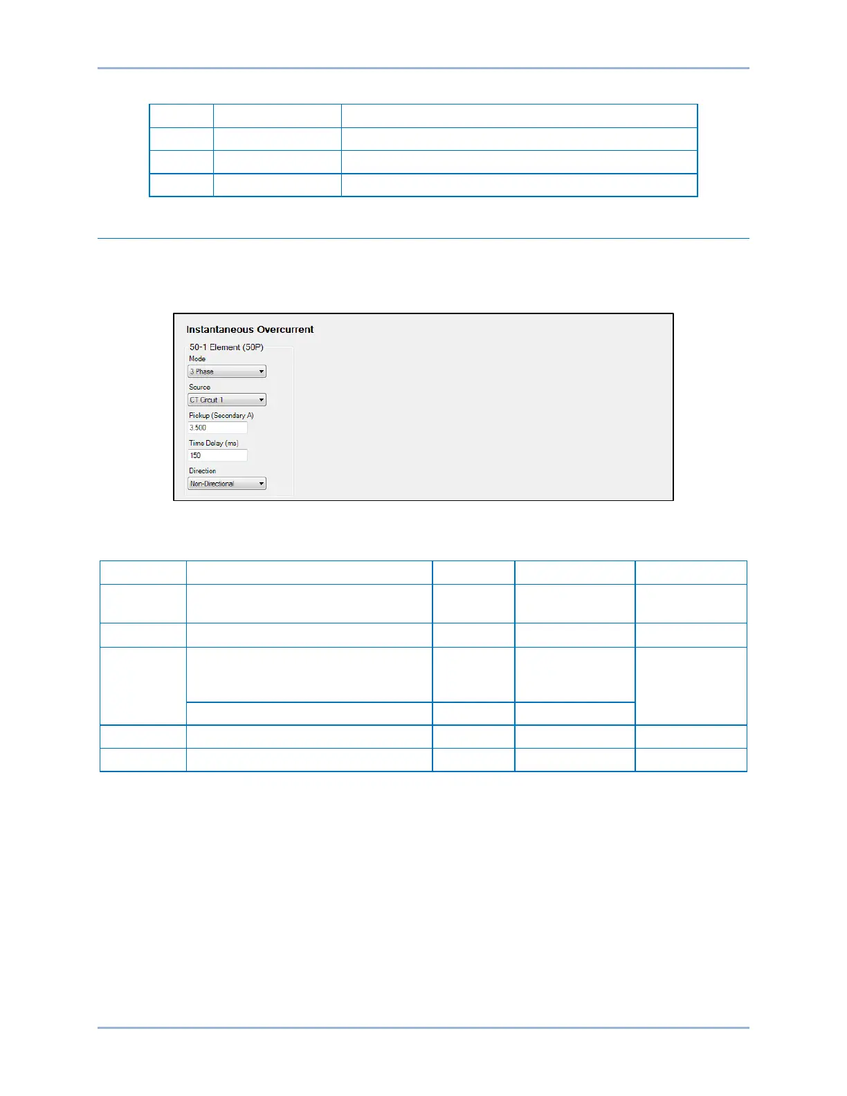
Instantaneous overcurrent element operational settings are configured on the Instantaneous Overcurrent
(50) settings screen (Figure 59) in BESTCOMSPlus. Setting ranges and defaults are summarized in
Table 30.
Figure 59. Instantaneous Overcurrent Settings Screen
Table 30. Operational Settings
Setting
Range
Increment
Unit of Measure
Default
Mode
Disabled, IA, IB, IC, 3 Phase,
3I0, I1, I2, IG, or Unbalance
n/a n/a Disabled
Source*
CT Circuit 1 or CT Circuit 2
n/a
n/a
CT Circuit 1
Pickup
0 or 0.5 to 150 (5A CTs)
0 or 0.1 to 30 (1A CTs)
0 or 0.01 to 7.5 (SEF)
varies amps
0
2 to 100 (Unbalance mode)
1
percent
Time Delay
0 to 60,000
varies
milliseconds
0
Direction
Forward, Reverse, or Non-Directional
n/a
n/a
Non-Directional
* For protection systems equipped with two sets of CTs.
BE1-11g Instantaneous Overcurrent (50) Protection

Table of Contents

Questions and Answers:

Question and Answer IconNeed help?

Do you have a question about the Basler BE1-11g and is the answer not in the manual?

Basler BE1-11g Specifications

General IconGeneral
BrandBasler
ModelBE1-11g
CategoryRelays
LanguageEnglish

Related product manuals