424 9424200994 Rev N
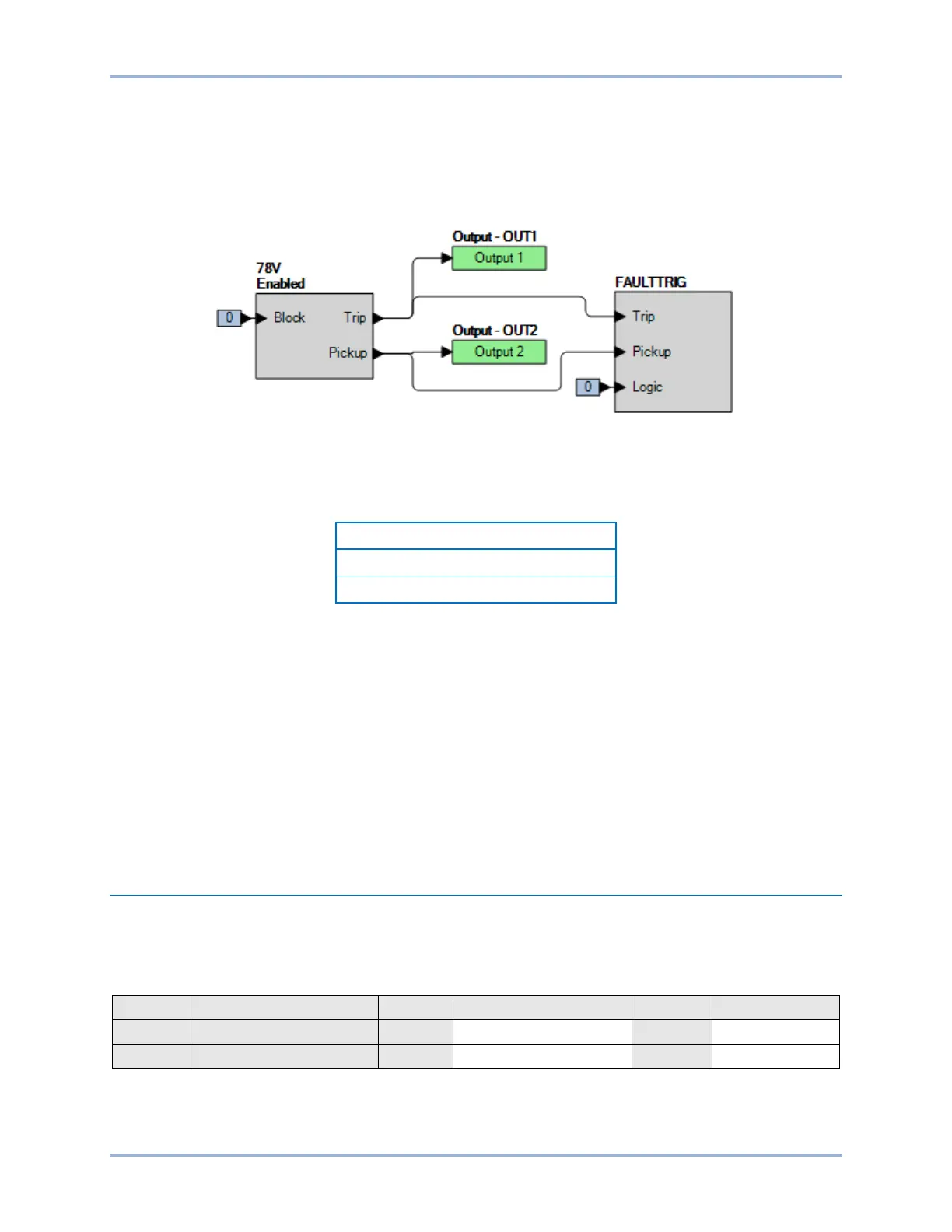
Step 2: Use BESTCOMSPlus to configure the BESTlogicPlus programmable logic shown in Figure 291.
• Blocking is disabled.
• OUT1 closes for 78V Trip.
• OUT2 closes for 78V Pickup.
• Fault recording is enabled.
Figure 291. BESTlogicPlus Settings
Step 3: Use BESTCOMSPlus to open the Protection, Voltage, Vector Jump (78V) screen and send the
first row of test settings in Table 173 to the BE1-11g.
Table 173. Pickup Test Settings
Step 4: Prepare to monitor the 78V function operation. Operation can be verified by monitoring OUT1
(see Figure 291).
Step 5: Connect and apply a three-phase 120 V phase-phase voltage source to terminals C13 (A-
phase) and C16 (Neutral).
Step 6: Apply a ±20 degree step change to the A-phase voltage angle. Verify OUT1 closes and record
the pickup. Verify that there is a 78V target on the front-panel display. Total time to trip should
be 150 ms or less. Remove the A-phase voltage angle. Verify that OUT1 opens and record the
reset. Reset the target.
Step 7: Verify the pickup accuracy and reset for a pickup setting of 90° as listed in Table 173. Record
the results.
Step 8: (Optional.) Repeat steps 1 through 7 for settings group 1, 2, and 3.
Functional Test Report
Pickup Verification
Pickup Setting Range = 2 to 90°
Pickup Accuracy = ±1°
Vector Jump (78V) Test BE1-11g