9424200994 Rev N 315
A Page Setup icon is also provided on the BESTlogicPlus Programmable Logic toolbar allowing you to
select Paper Size, Paper Source, Orientation, and Margins.
Clearing the On-Screen Logic Diagram
Click the Clear button to clear the on-screen logic diagram on all logic pages and start over.
BESTlogic™Plus Examples
Example 1 - OR Gate Connections
Figure 238 illustrates a typical OR gate connection. In this example, OUT5 will become active when either
the Major Alarm OR the Minor Alarm OR both is true.
Figure 238. Example 1 - OR Gate Connections
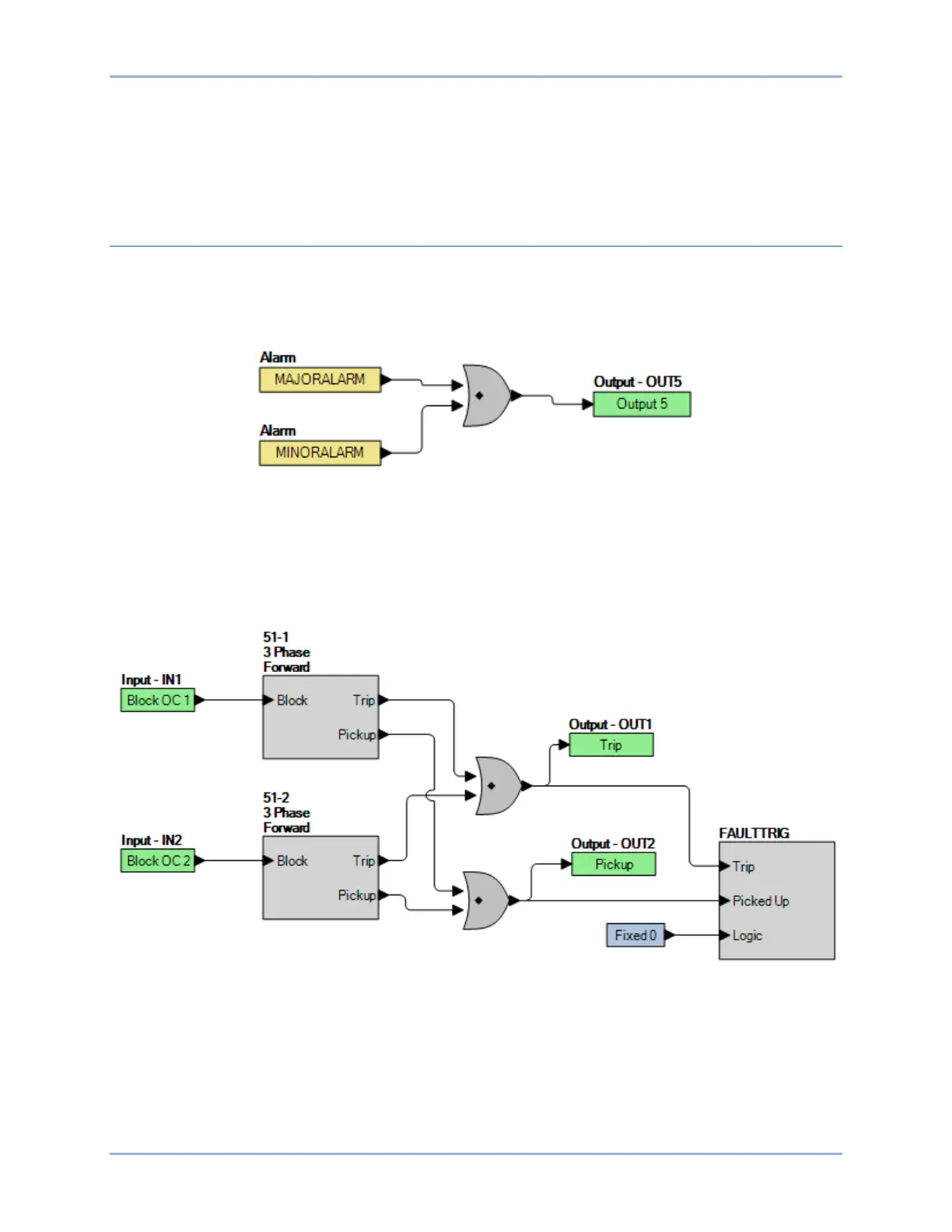
Example 2 - Inverse Overcurrent Logic Diagram
Figure 239 illustrates a typical logic diagram of two inverse overcurrent elements set up to trip outputs
and trigger fault reports. The 51-1 function is blocked when IN1 is true. The 51-1 function is blocked when
IN2 is true. OUT1 is true when either the 51-1 or 51-2 is in a trip condition. OUT2 is true when either the
51-1 or 51-2 is in a pickup condition. The fault trigger logic block ensures that faults are recorded.
Figure 239. Example 2 - Inverse Overcurrent Logic Diagram
BE1-11g BESTlogic™Plus