9424200994 Rev N 503
Step 4: Gradually decrease the magnitude all three phase voltages until OUT2 closes. Record the time
to trip (OUT1 closes). Verify that the 21-1-AB, 21-1-BC, and 21-1-CA targets are displayed on
the front-panel display. Increase the voltage until OUT2 opens. Reset the target.
Step 5: Repeat step 4 for the time delays in the second and third rows of Table 231. Record the results.
Timing accuracy is 0.5% or 2 cycles, whichever is greater.
Step 6: (Optional.) Repeat steps 1 through 5 for settings group 1, 2, and 3.
Step 7: (Optional.) Repeat steps 1 through 6 for 21-2.
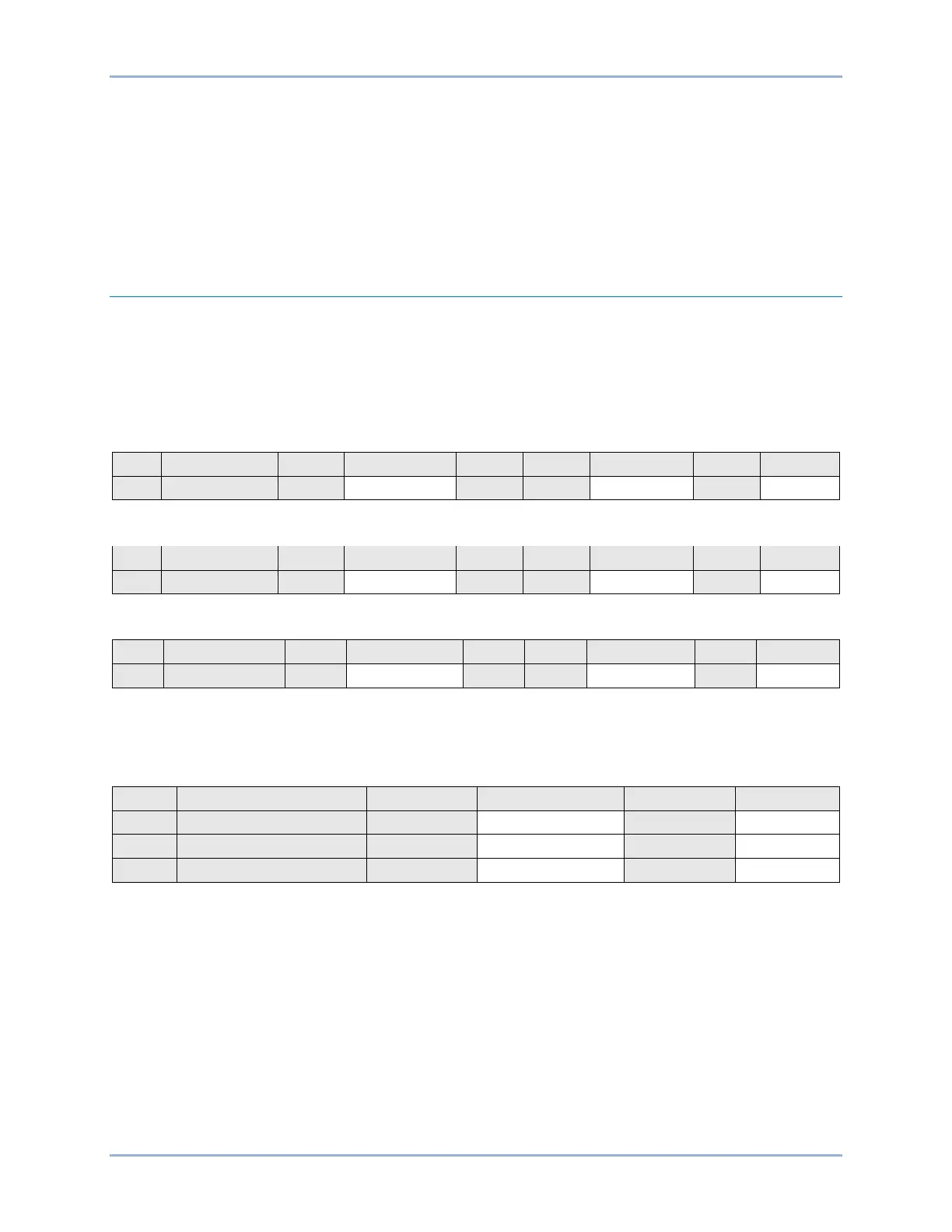
Functional Test Report
Pickup Verification Table 2 Row 1
Diameter Setting Range = 0 – 500 secondary Ω
Pickup Accuracy = ±2% or ±0.1 Ω, whichever is greater
Reset Hysteresis = 105% of the diameter setting
Reset Accuracy = ±2% or ±0.1 Ω, whichever is greater
Pickup Verification Table 2 Row 2
Pickup Verification Table 2 Row 3
Timing Verification
Time Delay Range = 0 to 300,000 ms
Timing Accuracy = ±0.5% or ±2 cycles, whichever is greater
BE1-11g Distance (21) Test