9424200994 Rev N 419
Step 5: Connect and apply a single-phase, 120 Vac, 3
rd
harmonic voltage source to the Vx input,
terminals C17 (polarity) and C18 (non-polarity).
Step 6: Slowly increase the voltage until OUT2 closes and record the pickup. Verify that there is a 59X-
1-3RD target on the front-panel display. Slowly decrease the voltage until OUT2 opens and
record the dropout. Reset the target.
Step 7: Verify the pickup and dropout accuracy at 70 Vac for a pickup setting of 75 V and 25 Vac for a
pickup setting of 30 V as listed in Table 170. Record the results.
Step 8: (Optional.) Repeat steps 1 through 7 for the B-phase and C-phase voltage inputs.
Step 9: (Optional.) Repeat steps 1 through 8 for settings group 1, 2, and 3.
Step 10: (Optional.) Repeat steps 1 through 9 for 59X-2, 59X-3, and 59X-4.
Timing Verification (Vx Third Harmonic Mode)
Step 1: Use BESTCOMSPlus to open the Protection, Voltage, Overvoltage (59X-1) screen and send
the first row of test settings in Table 171 to the BE1-11g for settings group 0.
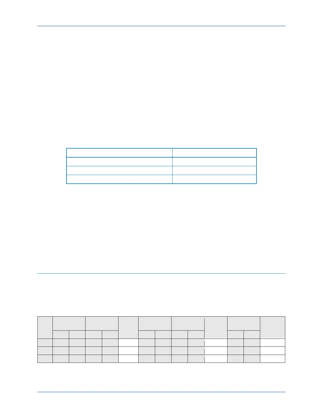
Table 171. Timing Test Settings (Vx Third Harmonic Mode)
Step 2: Prepare to monitor the 59X-1 timings. Timing accuracy is verified by measuring the elapsed
time between a sensing voltage change and OUT1 closing.
Step 3: Connect and apply a 120 Vac, single-phase, 3
rd
harmonic voltage source to terminals C17
(polarity) and C18 (non-polarity).
Step 4: Step the voltage up to 130 volts. Measure the time delay and record the result.
Step 5: Repeat step 4 for the 5,000 ms and 10,000 ms time delay settings of Table 171. Record the
results.
Step 6: (Optional.) Repeat steps 1 through 5 for settings group 1, 2, and 3.
Step 7: (Optional.) Repeat steps 1 through 6 for 59X-2, 59X-3, and 59X-4.
Functional Test Report
Pickup Verification (3V0 Mode)
Pickup Setting Range = 1 to 150 V
Pickup Accuracy = ±2% or ±1 V, whichever is greater
Dropout/Pickup Ratio = 98% ±1%
Step
Low
Actual
Pickup
High
Low*
Actual
Dropout
High*
Pass/Fail
* Dropout range is calculated from the pickup setting and may need adjusted based on actual pickup.
† VA Low and High values are calculated as VA=3V0+150 V nominal.
BE1-11g Auxiliary Overvoltage (59X) Test