9424200994 Rev N 161
A Block Tag alarm indicates when a block tag is in place. Refer to the Alarms chapter for information on
how to program alarms.
Logic Connections
Virtual control switch element logic connections are made on the BESTlogicPlus screen in
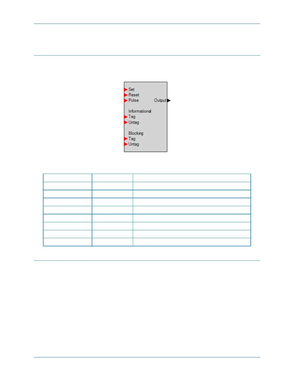
BESTCOMSPlus. The virtual control switch element logic block is illustrated in Figure 100. Logic inputs
and outputs are summarized in Table 61.
Figure 100. Virtual Control Switch Element Logic Block
Table 61. Logic Inputs and Outputs
Sets the state of the output to true
Sets the state of the output to false
Momentarily changes state of the output
Sets an informational tag on the 43 element
Removes the informational tag from the 43 element
Sets a blocking tag on the 43 element
Removes the blocking tag from the 43 element
True when the 43 element is set
Operational Settings
Virtual control switch element operational settings are configured on the Virtual Control Switches (43)
settings screen (Figure 101) in BESTCOMSPlus. Setting ranges and defaults are summarized in Table
62.
BE1-11g Virtual Control Switches (43)