388 9424200994 Rev N
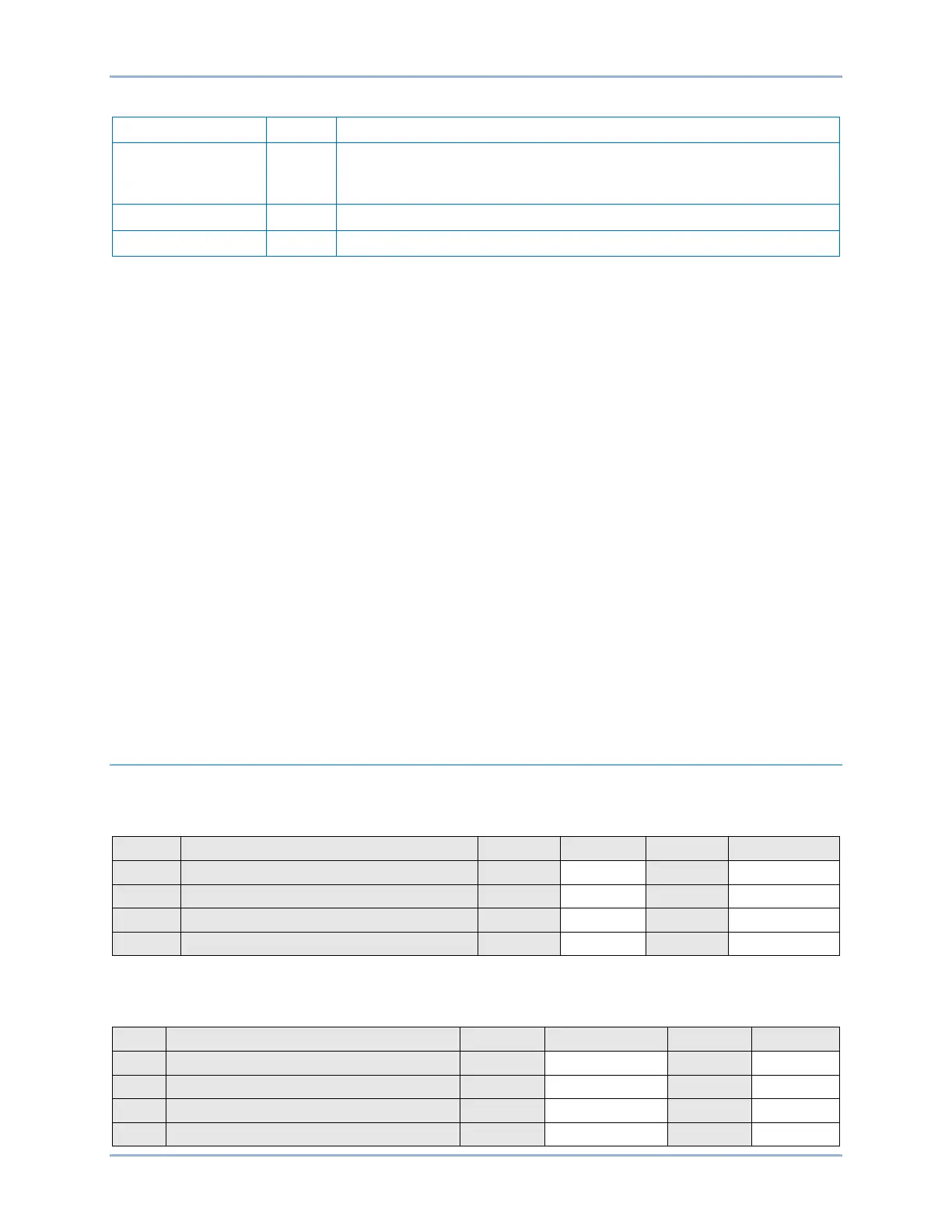
Table 135. Inverse Time and Definite Time Pickup Test Settings (25)
Sets voltage difference to 10 V (10% of nominal, nominal = 100 V).
Nominal settings are defined on the System Parameters, Power
System screen in BESTCOMSPlus.
Sets slip angle to 10 degrees
Sets slip frequency to 0.3 Hz
Step 2: Prepare to monitor the 25 function operation. Operation can be verified by monitoring OUT1.
Step 3: As in the previous test, connect BE1-11g terminals C13 (A-phase), C14 (B-phase), and C15 (C-
phase) together. Apply a 120 Vac, 50 or 60 hertz ac, 0 degree voltage source (Line VTP) to the
three jumpered terminals and the neutral terminal (C16).
Step 4: Apply a second 120 Vac, 50 or 60-hertz ac, 0 degree voltage source (Auxiliary VTX) to C17 and
C18. OUT1 should close verifying the 25 output for a Slip Angle of 0 degrees, 0 Voltage
Difference, and 0 Slip Frequency.
Step 5: Decrease the Auxiliary voltage input (VTX) until OUT1 opens. Slowly increase the voltage until
OUT1 closes. Record the result.
Step 6: Repeat step 5 for the Line voltage input (VTP). Return voltage inputs to 120 Vac, 50 or 60-hertz,
0 degrees. Record the result.
Step 7: Swing the angle between voltage source 1 and 2 until the OUT1 opens. Slowly decrease the
angle until OUT1 closes. Pickup should occur on the leading and lagging side of 0 degrees.
Dropout should occur on the leading and lagging side of 0 degrees. Record the results.
Step 8: With the Auxiliary Voltage set at nominal frequency, step change the frequency of the Line
voltage input by –0.25 hertz (59.75 on a 60-hertz BE1-11g). Note that OUT1 is closing and
opening based on a slip rate of 0.25 hertz. Decrease the frequency until OUT1 stays open.
Record the result. Also, check on the fast side (60.25 for a 60-hertz BE1-11g). Record the
result.
Step 9: Repeat step 8 for the Auxiliary Voltage input. Record the results.
Step 10: (Optional.) Repeat steps 3 through 9 for settings group 1, 2, and 3.
Functional Test Report
VTP and VTX Live Voltage, Dead Voltage Pickup Test (25 Voltage Monitor)
Accuracy = ±2%
VTP - Dead V Dropout - 55.0 V
VTP - Live V Pickup - 90.0 V
VTX - Dead V Dropout - 55.0 V
VTX - Live V Pickup - 90.0 V
Live/Dead Dropout Timing Verification (25 Voltage Monitor)
Accuracy = ±0.5% or ±2 cycles, whichever is greater
VTP - Dead V Dropout Delay - 50 ms
VTP - Live V Dropout Delay - 50 ms
VTP - Dead V Dropout Delay - 2000 ms
VTP - Live V Dropout Delay - 2000 ms
Sync-Check (25) Test BE1-11g