632 9424200994 Rev N
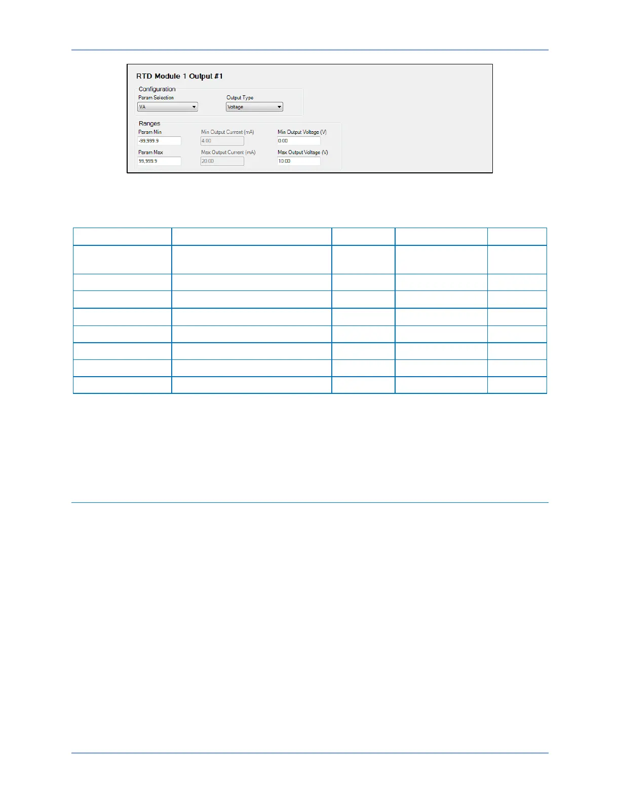
Figure 386. Module 1 Output #1 Screen
Table 258 summarizes the configuration settings for remote analog outputs.
Table 258. Configuration Settings for Remote Analog Outputs
Param Selection
Voltages, Currents, Frequency,
Power, etc.
n/a n/a VA
Remote Analog Output Metering
Analog output metering values are obtained through BESTCOMSPlus by using the Metering Explorer to
open the Analog Metering, Analog Outputs tree branch. BESTCOMSPlus must be online with the BE1-
11g to view analog output metering. Alternately, values can be obtained through the front-panel display by
navigating to Metering > Analog Metering > Analog Output.
Remote RTDs Configuration
The RTD module provides 12 RTD inputs. The BE1-11g supports two RTD modules at once. The RTDs
are always monitored and their status is displayed on the appropriate metering screens. The BE1-11g
reports Out of Range when an RTD module is disconnected.
Protection settings for remote RTDs are described in the Resistance Temperature Detector (49RTD)
Protection chapter.
Configuration Settings
BESTCOMSPlus Navigation Path: Settings Explorer, Programmable Inputs, Remote RTD
HMI Navigation Path: Settings Explorer, RTD Types
Configuration settings are made using the BE1-11 plugin for BESTCOMSPlus. Before making
configuration settings, remote module communications must be configured on the System Parameters,
Remote Module Communications screen. To program the configuration settings, use the Settings
Explorer to open the Programmable Outputs, Remote RTD, RTD Type Selection tree branch and select
RTD Type Selection. Use the drop-down menu to select RTD Type. Refer to Figure 387.
RTD Module BE1-11g