502 9424200994 Rev N
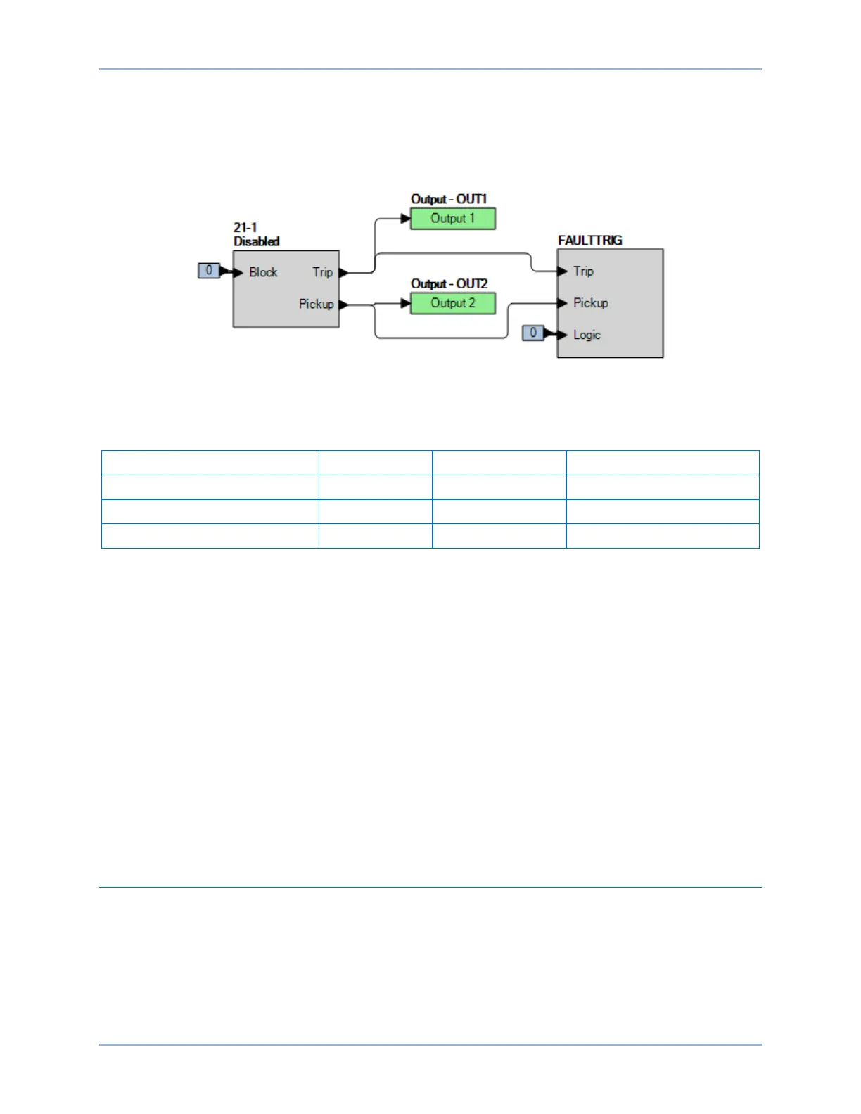
Step 2: Use BESTCOMSPlus to configure the BESTlogicPlus programmable logic shown in Figure 312.
• Blocking is disabled.
• OUT1 closes for 21-1 Trip.
• OUT2 closes for 21-1 Pickup.
• Fault recording is enabled.
Figure 312. BESTlogicPlus Settings
Step 3: Use BESTCOMSPlus to open the Protection, Impedance, Distance (21) screen and verify the
first row of test settings in Table 231 for 21-1.
Table 231. Pickup Test Settings
Step 4: Prepare to monitor the 21-1 function operation. Operation can be verified by monitoring OUT1
(see Figure 312).
Step 5: Connect and apply a balanced three-phase current of 5 Aac to terminals D1 through D6 and a
balanced three-phase voltage of 69.28 V phase-neutral voltage source to terminals C13 (A-
phase), C14 (B-phase), C15 (C-phase), and C16 (Neutral).
Step 6: Gradually decrease the magnitude of all three phase voltages until OUT2 closes and record the
pickup. This should occur at 45.282 V ±1.569 V. Gradually increase the voltage until OUT2
opens and record the reset. This should occur at approximately 47 V. Reset the target.
Step 7: Verify the pickup and reset accuracy for all settings as listed in Table 231. Reference the
functional test report below for the remaining voltage values to be used. Record the results.
Pickup accuracy is ±2% or 0.1 Ω of the calculated trip point on the mho circle, whichever is
greater. Impedance values for this test have been converted to measureable phase-neutral
voltages.
Step 8: (Optional.) Repeat steps 1 through 7 for settings group 1, 2, and 3.
Step 9: (Optional.) Repeat steps 1 through 8 for 21-2.
Timing Verification
Step 1: Use BESTCOMSPlus to open the Protection, Impedance, Distance (21) screen and send the
first row of test settings in Table 231 to the 21-1 element for settings group 0.
Step 2: Prepare to monitor the 21-1 timings. Timing accuracy is verified by measuring the elapsed time
between OUT2 (pickup) and OUT1 (trip) closing.
Step 3: Connect and apply balanced three-phase 5 A to terminals D1 through D6 and a balanced three-
phase 69.28 V phase-neutral voltage source to terminals C13 (A-phase), C14 (B-phase), C15
(C-phase), and C16 (Neutral).
Distance (21) Test BE1-11g