82 9424200994 Rev N
Logic Connections
Frequency element logic connections are made on the BESTlogicPlus screen in BESTCOMSPlus. The
frequency element logic block is illustrated in Figure 54. Logic inputs and outputs are summarized in
Table 26.
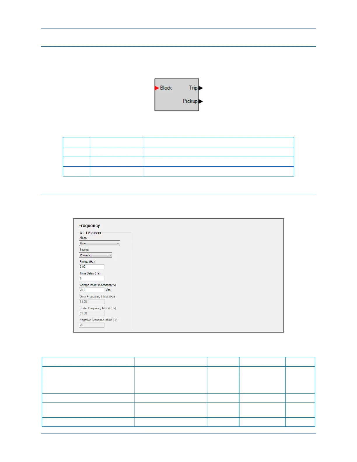
Figure 54. Frequency Element Logic Block
Table 26. Logic Inputs and Outputs
Disables the 81 function when true
True when the 81 element is in a trip condition
True when the 81 element is in a pickup condition
Operational Settings
Frequency element operational settings are configured on the Frequency settings screen (Figure 55) in
BESTCOMSPlus. Setting ranges and defaults are summarized in Table 27.
Figure 55. Frequency Settings Screen
Table 27. Operational Settings
Mode
Rate of Change,
Positive Rate of Change,
or Negative Rate of Change
n/a n/a Disabled
Pickup
0 or 0.2 to 20 for ROC mode
0 or 15 to 70 for O/U mode
0.01
hertz/sec (ROC)
hertz (O/U)
0
Frequency (81) Protection BE1-11g