9424200994 Rev N 71
element Block input to the desired logic in BESTlogicPlus. When the element is initially selected from the
Elements view, the default condition of the Block input is a logic 0.
Logic Connections
Auxiliary overvoltage element logic connections are made on the BESTlogicPlus screen in
BESTCOMSPlus. The auxiliary overvoltage element logic block is illustrated in Figure 50. Logic inputs
and outputs are summarized in Table 22.
Figure 50. Auxiliary Overvoltage Element Logic Block
Table 22. Logic Inputs and Outputs
Disables the 59X function when true
True when the 59X element is in a trip condition
True when the 59X element is in a pickup condition
Operational Settings
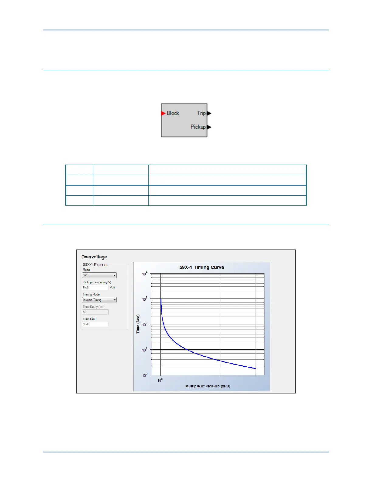
Auxiliary overvoltage element operational settings are configured on the Overvoltage (59X) settings
screen (Figure 51) in BESTCOMSPlus. Setting ranges and defaults are summarized in Table 23.
Figure 51. Auxiliary Overvoltage Settings Screen
BE1-11g Auxiliary Overvoltage (59X) Protection