126 9424200994 Rev N
Logic Connections
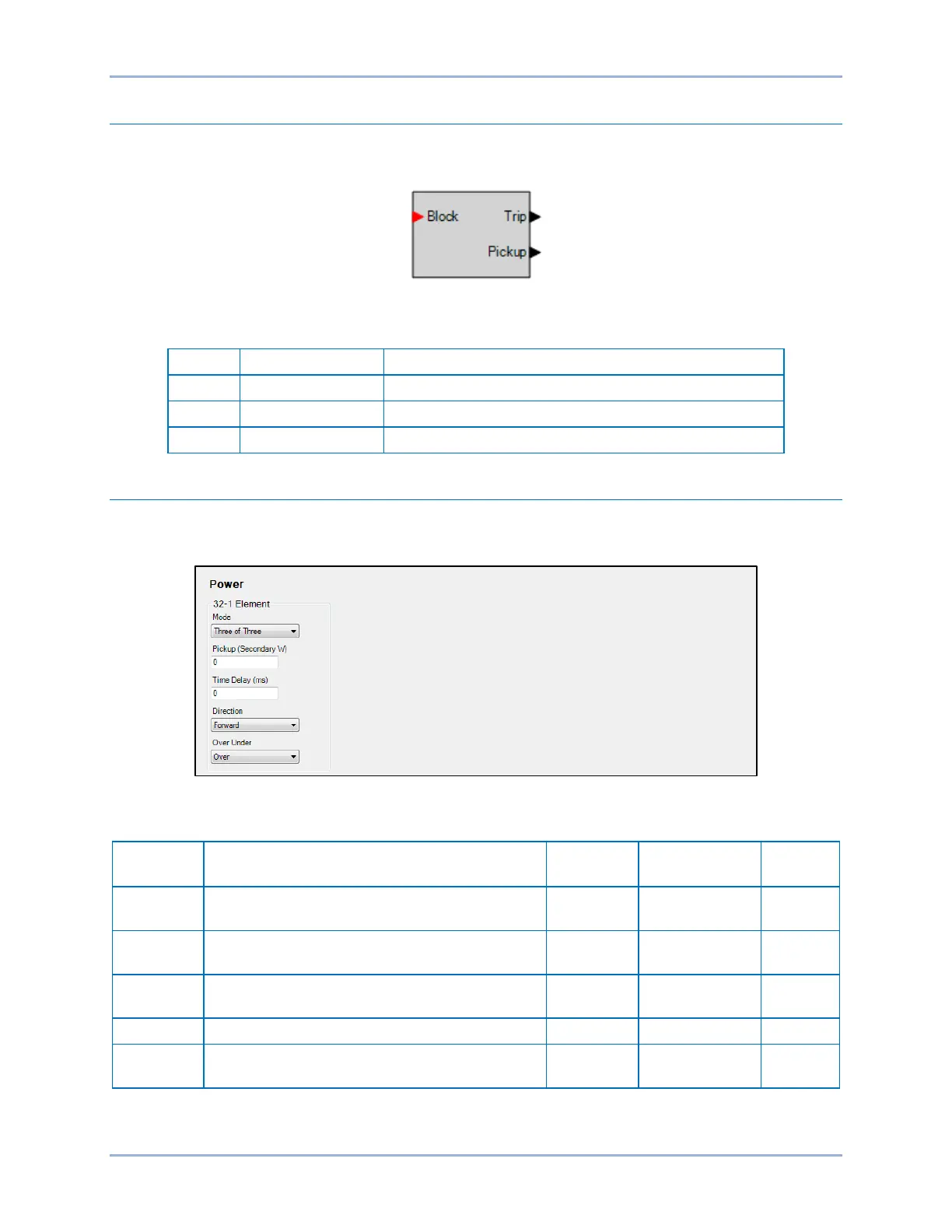
Power element logic connections are made on the BESTlogicPlus screen in BESTCOMSPlus. The power
element logic block is illustrated in Figure 78. Logic inputs and outputs are summarized in Table 44.
Figure 78. Power Element Logic Block
Table 44. Logic Inputs and Outputs
Disables the 32 function when true
True when the 32 element is in a trip condition
True when the 32 element is in a pickup condition
Operational Settings
Power element operational settings are configured on the Power (32) settings screen (Figure 79) in
BESTCOMSPlus. Setting ranges and defaults are summarized in Table 45.
Figure 79. Power Settings Screen
Table 45. Operational Settings
Setting Range Increment
Default
Mode
Disabled, One of Three, Two of Three, Three
of Three, or Total Power
n/a n/a Disabled
Pickup
0 or 1 to 6,000 (5A CTs)
0 or 1 to 1,200 (1A CTs)
varies watts 0
0 or 50 to 600,000 varies milliseconds 0
Over or Under n/a n/a Over
Power (32) Protection BE1-11g