450 9424200994 Rev N
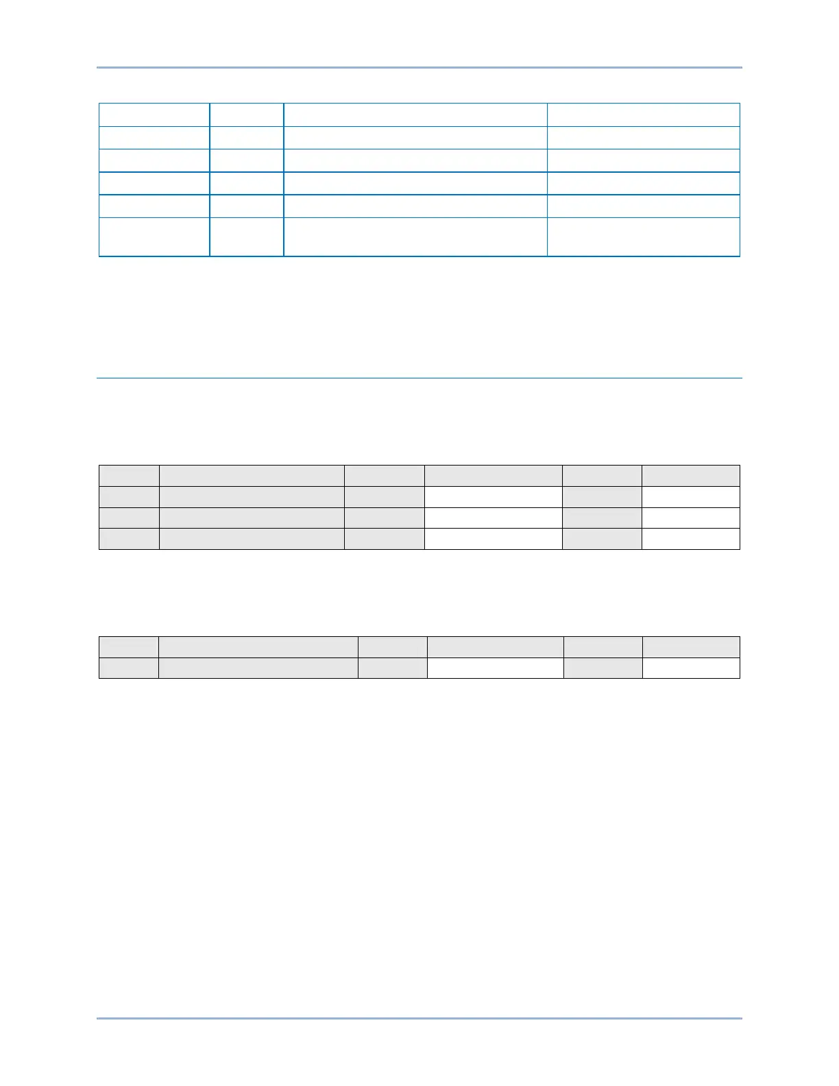
Table 195. Control Time Delay Settings
Protection, Current, Breaker Fail (50BF)
Protection, Current, Breaker Fail (50BF)
Sets ground pickup to 1 A
Protection, Current, Breaker Fail (50BF)
Sets control timer to 100 ms
Protection, Current, Breaker Fail (50BF)
Sets delay timer to 200 ms
Protection, Current, Instantaneous
Overcurrent (50-1)
Step 13: (Optional.) Repeat steps 1 through 12 for the B and C phase elements. Note: Set 50-1 mode to
IB for B-phase and IC for C-phase.
Step 14: (Optional.) Repeat steps 7 through 13 with CT Circuit 2 as the source for protection systems
equipped with two sets of CTs. In step 12, replace D1 with F1, D2 with F2, etc.
Functional Test Report
Delay Timer Verification
Delay Timer Range = 50 to 999 ms
Delay Timer Accuracy = ±0.5% or +1¼, −0.5 cycles, whichever is greater
Control Timer Verification
Control Timer Range = 50 to 99 ms
Control Timer Accuracy = ±0.5% or ½ cycle, whichever is greater
Breaker Fail (50BF) Test BE1-11g