9424200994 Rev N 393
Step 2: Prepare to monitor the 27P-1 timings. Timing accuracy is verified by measuring the elapsed
time between a sensing voltage change and OUT1 closing.
Step 3: Connect and apply a 120 Vac, three-phase voltage source to terminals C13 (A-phase), C14 (B-
phase), C15 (C-phase), and C16 (Neutral).
Step 4: Step the A-phase voltage down to 110 volts. Measure the time delay and record the result.
Step 5: Repeat step 4 for the 5,000 ms and 10,000 ms time delays of Table 138. Record the results.
Step 6: (Optional.) Repeat steps 1 through 5 for the B-phase and C-phase voltage inputs. Note: Be sure
to enable proper target for each phase being tested.
Step 7: (Optional.) Repeat steps 1 through 6 through 6 for settings group 1, 2, and 3.
Step 8: (Optional.) Repeat steps 1 through 7 for 27P-2, 27P-3, 27P-4, and 27P-5.
Functional Test Report
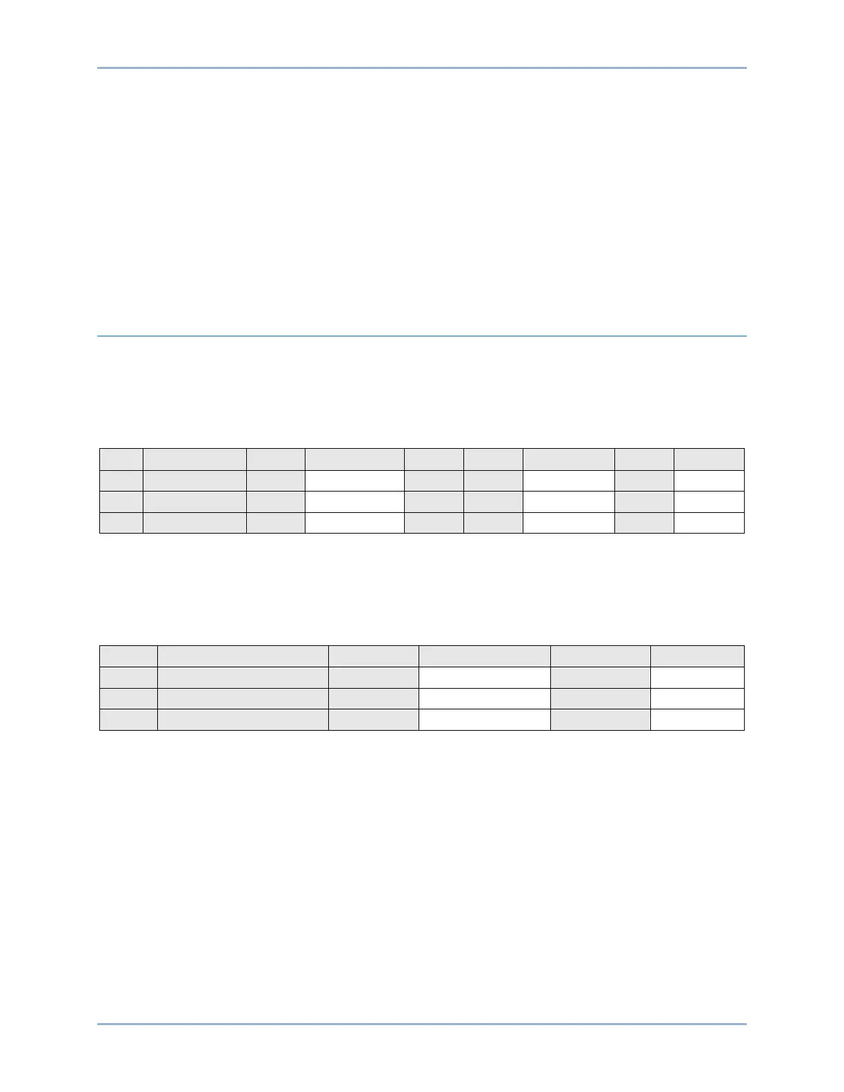
Pickup Verification
Pickup Setting Range = 1 to 300 V
Pickup Accuracy = ±2% or ±1 V, whichever is greater
Reset/Pickup Ratio = 102% ±1%
* Reset range is calculated from the pickup setting and may need adjusted based on actual pickup.
Timing Verification
Time Delay Range = 50 to 600000 ms
Timing Accuracy = ±0.5% or ±2 cycles, whichever is greater
BE1-11g Phase Undervoltage (27P) Test