9424200994 Rev N 349
Settings
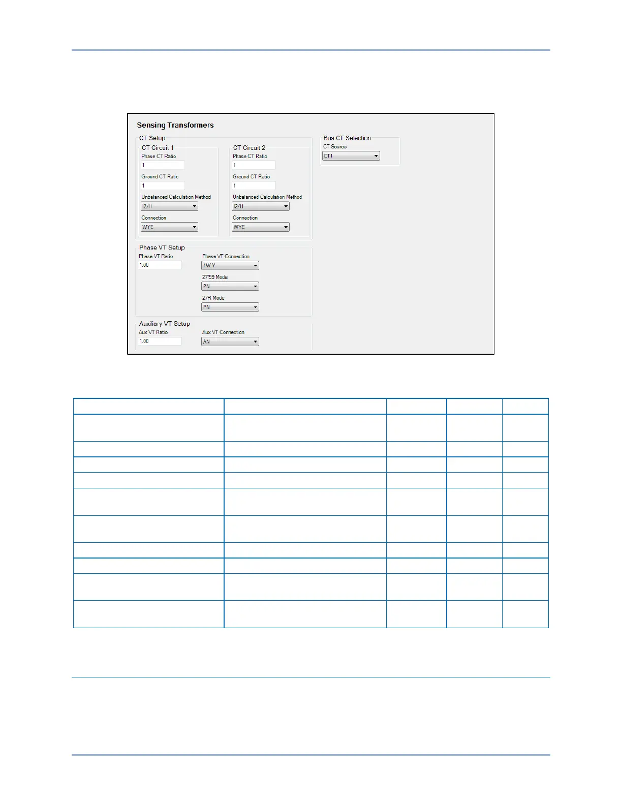
Sensing transformers settings are configured on the Sensing Transformers settings screen (Figure 269)
in BESTCOMSPlus. Setting ranges and defaults are summarized in Table 113.
Figure 269. Sensing Transformers Settings Screen
Table 113. Sensing Transformers Settings
Phase/Ground CT Ratio 1 to 50,000 0.01
1
Unbalanced Calculation Mode
Phase VT Ratio 1 to 10,000 0.01
1
Phase VT Connection
AB, BC, CA, AN, BN, CN, 3W-D,
or 4W-Y
n/a n/a 4W-Y
Aux VT Ratio 1 to 10,000 0.01
1
Aux VT Connection
AB, BC, CA, AN, BN, CN, or
Ground
n/a n/a AN
* For protection systems equipped with two sets of CTs.
Transformer Setup
The BE1-11g requires information about the transformer windings to provide differential metering and
differential protection. See the Phase Current Differential (87) Protection chapter for more information.
Transformer setup is accomplished on the Sensing Transformers settings screen (Figure 270) in
BESTCOMSPlus. Setting ranges and defaults are summarized in Table 114.
BE1-11g Configuration
 Loading...


