418 9424200994 Rev N
Step 5: Repeat step 4 for the 5,000 ms and 10,000 ms time delay settings of Table 168. Record the
results.
Step 6: (Optional.) Repeat steps 1 through 5 for settings group 1, 2, and 3.
Step 7: (Optional.) Repeat steps 1 through 6 for 59X-2, 59X-3, and 59X-4.
Pickup Verification (Vx Third Harmonic Mode)
Step 1: Use BESTCOMSPlus to send the operational settings in Table 169 to the BE1-11g. Reset all
targets.
Table 169. Operational Settings (Vx Third Harmonic Mode)
System Parameters, Sensing
Transformers
Sets auxiliary VT ratio to 1
System Parameters, Sensing
Transformers
Sets auxiliary VT connection to
AN
Protection, Voltage,
Overvoltage (59X-1)
Enables 59X-1 function for Vx
Third Harmonic mode
Protection, Voltage,
Overvoltage (59X-1)
Target Configuration, Targets
Enables Vx Third Harmonic
target for 59X-1
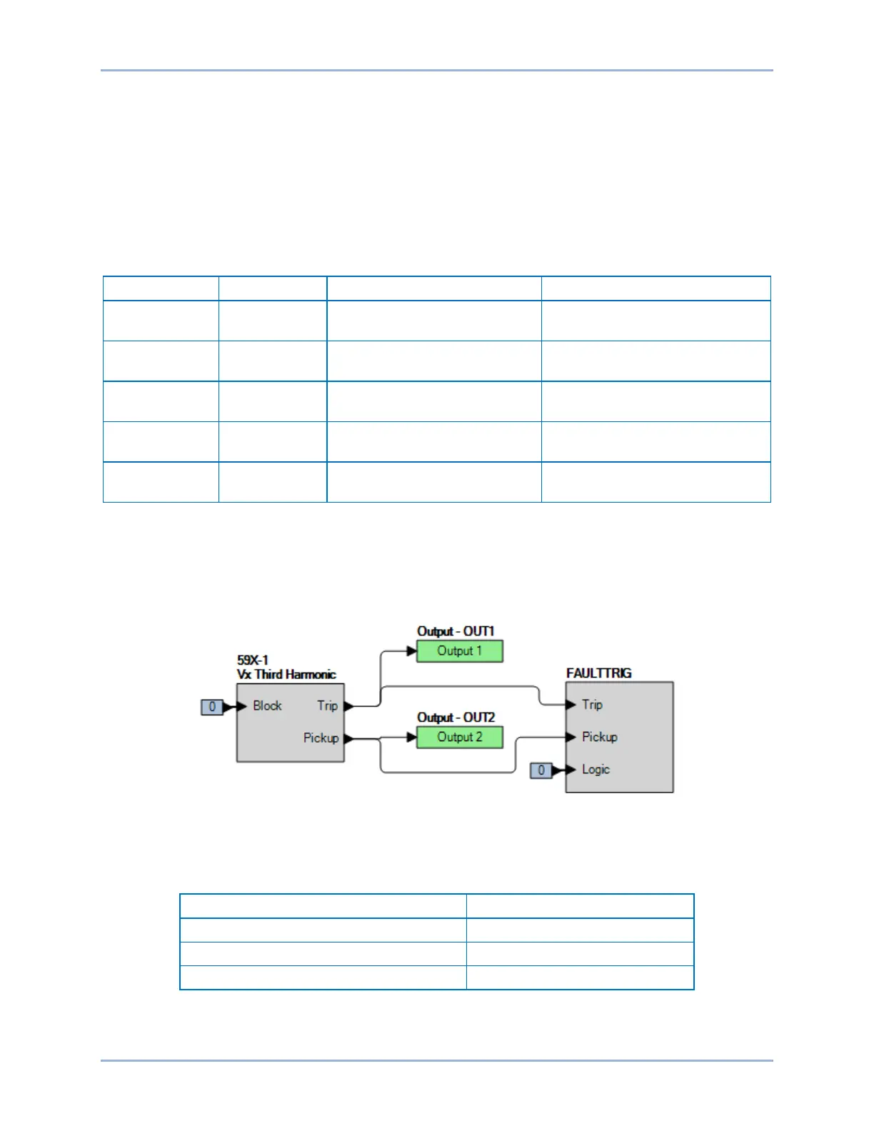
Step 2: Use BESTCOMSPlus to configure the BESTlogicPlus programmable logic shown in Figure 290.
• Blocking is disabled.
• OUT1 closes for 59X-1 Trip.
• OUT2 closes for 59X-1 Pickup.
• Fault recording is enabled.
Figure 290. BESTlogicPlus Settings (Vx Third Harmonic Mode)
Step 3: Use BESTCOMSPlus to open the Protection, Voltage, Overvoltage (59X-1) screen and send
the first row of test settings in Table 170 to the BE1-11g.
Table 170. Pickup Test Settings (Vx Third Harmonic Mode)
Step 4: Prepare to monitor the 59X-1 function operation. Operation can be verified by monitoring OUT2
(see Figure 290).
Auxiliary Overvoltage (59X) Test BE1-11g
 Loading...


