9424200994 Rev N 417
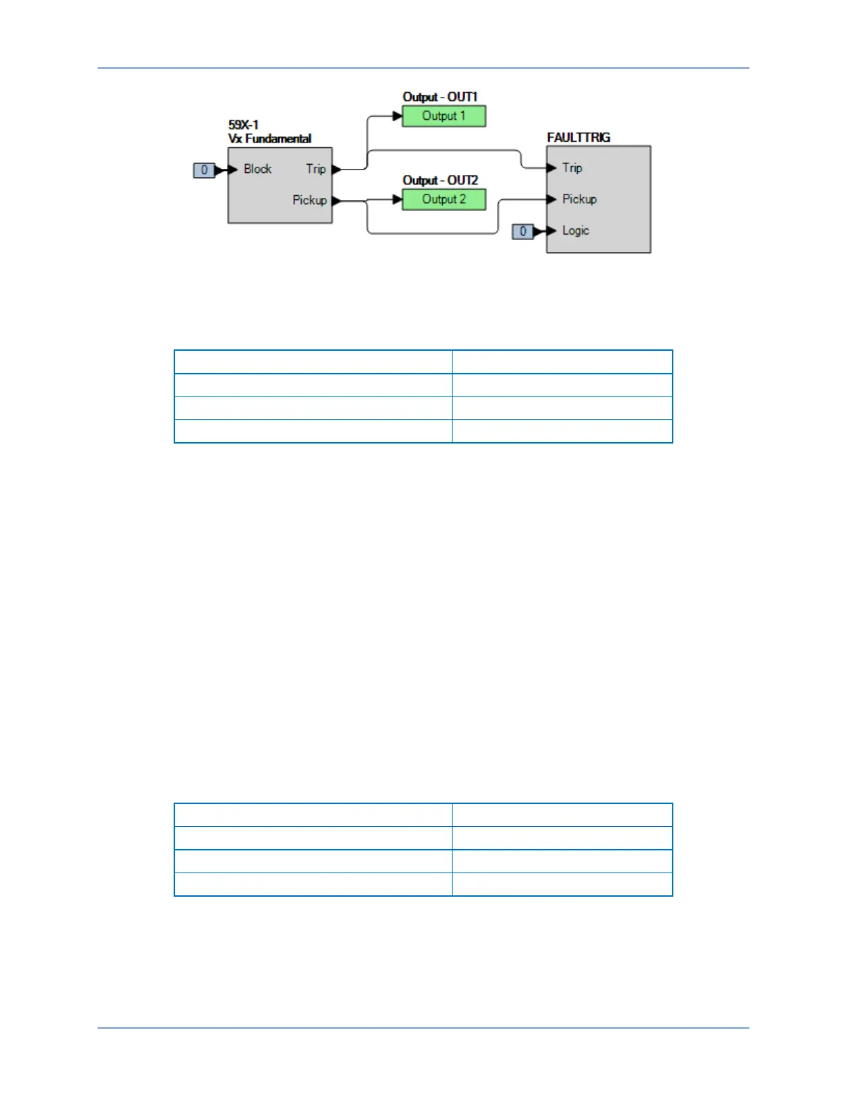
Figure 289. BESTlogicPlus Settings (Vx Fundamental Mode)
Step 3: Use BESTCOMSPlus to open the Protection, Voltage, Overvoltage (59X-1) screen and send
the first row of test settings in Table 167 to the BE1-11g.
Table 167. Pickup Test Settings (Vx Fundamental Mode)
Step 4: Prepare to monitor the 59X-1 function operation. Operation can be verified by monitoring OUT2
(see Figure 289).
Step 5: Connect and apply a 120 Vac, single-phase voltage source to the Vx input, terminals C17
(polarity) and C18 (non-polarity).
Step 6: Slowly increase the voltage until OUT2 closes and record the pickup. Verify that there is a 59X-
1-AUX target on the front-panel display. Slowly decrease the voltage until OUT2 opens and
record the dropout. Reset the target.
Step 7: Verify the pickup and dropout accuracy at 70 Vac for a pickup setting of 75 V and 25 Vac for a
pickup setting of 30 V as listed in Table 167. Record the results.
Step 8: (Optional.) Repeat steps 1 through 7 for the B-phase and C-phase voltage inputs.
Step 9: (Optional.) Repeat steps 1 through 8 for settings group 1, 2, and 3.
Step 10: (Optional.) Repeat steps 1 through 9 for 59X-2, 59X-3, and 59X-4.
Timing Verification (Vx Fundamental Mode)
Step 1: Use BESTCOMSPlus to open the Protection, Voltage, Overvoltage (59X-1) screen and send
the first row of test settings in Table 168 to the BE1-11g for settings group 0.
Table 168. Timing Test Settings (Vx Fundamental Mode)
Step 2: Prepare to monitor the 59X-1 timings. Timing accuracy is verified by measuring the elapsed
time between a sensing voltage change and OUT1 closing.
Step 3: Connect and apply a 120 Vac, single-phase voltage source to terminals C17 (polarity) and C18
(non-polarity).
Step 4: Step the voltage up to 130 volts. Measure the time delay and record the result.
BE1-11g Auxiliary Overvoltage (59X) Test
 Loading...


